Instrument Functions
NRP2
115
User Manual 1173.9140.02 ─ 07
In full height window, the R&S
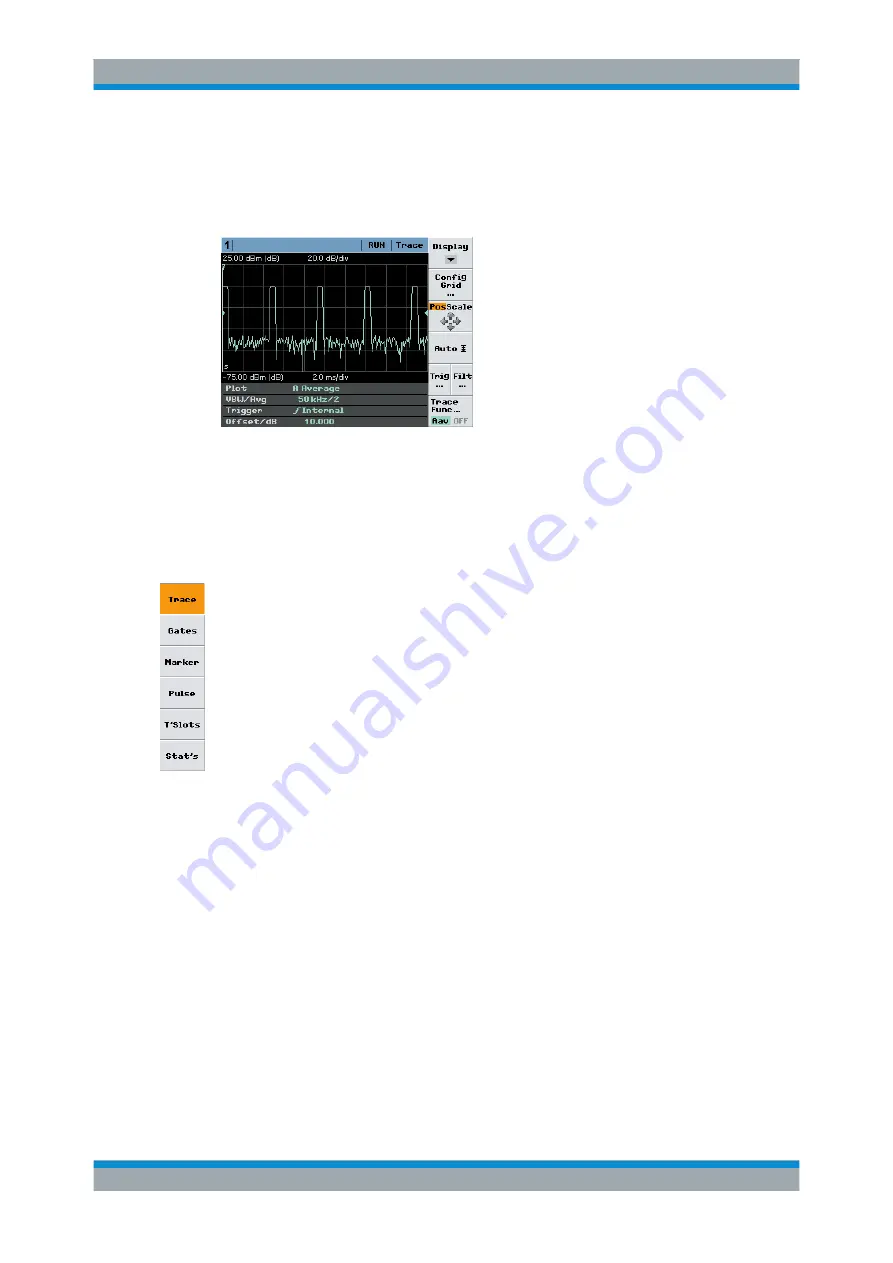
NRP2 provides additional control elements such as trig-
ger, marker or scale-setting parameters in the control panel on the right of the screen.
At the bottom of the screen, info panels indicate measurement results or instrument
settings.
Fig. 4-45: Trace window, full height window with control elements
The trace control panel covers various functions and parameters to configure the trace
measurement result. It changes according to the specific display mode.
By default, the meter displays the "Trace" display mode with the corresponding control
panel. Further display modes are set via the "Display" softkey.
Display
Opens the control panel for selecting the measurement mode for trace display.
See the following sections for more information:
"Trace"
shows the trace display mode and the corresponding control panel,
on
.
"Gates"
Gates display mode, on page 120
"Marker"
Marker display mode, on page124
"Pulse"
Pulse display mode, on page 126
"T'Slots"
T'Slots display mode, on page 131
"Stat's"
Stat's display mode, on page 135
4.5.3 Trace display mode
In the "Trace" mode, you can make all the settings that determine the position and the
size of the screen window, the type of display ("Peak", "Max Hold" etc.), "Trig"gering
and "Filt"ering.
► Select "Trace" in the control panel opened via the Window
→
Graph
→
"Display" panel ("Trace&Statistics" sensor mode).
Displaying traces
北京海洋兴业科技股份有限公司(证券代码:839145)
电话:010-62176775
网址:www.hyxyyq.com


