background image


- 20 -


3. 

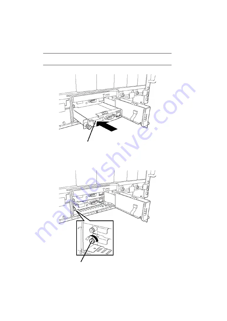
Locate the slot to install the EM card. Insert the EM card into the slot while pushing the 
handle. 

NOTE:

 When removing the EM card, hold the handle and pull the EM 

card out from the slot. 


4. 

Secure the EM card to the Blade Enclosure by using the thumb nut located at the left end 
of the card. 


Thumb nut 

Handle 

Summary of Contents for N8405-019

Page 1: ...N8405 019 019A EM Card User s Guide SIGMABLADE Monitor Operation Guide OSD On Screen Display Operation Guide 18th Edition 4 2016 ...

Page 2: ...tive trademark owners CE Statement Warning This is a Class A product In domestic environment this product may cause radio interference in which case the user may be required to take adequate measures EN55022 BSMI Statement MIC Statement 1 EM Card EXP462A 2 NEC Corporation 3 2006 11 4 NEC Computertechno Ltd JAPAN Notes 1 No part of this manual may be reproduced in any form without the prior written...

Page 3: ... ignored Precautions and notices against hazards are presented with one of the following three symbols The individual symbols are defined as follows This symbol indicates the presence of a hazard if the instruction is ignored An image in the symbol illustrates the hazard type Attention This symbol indicates prohibited actions An image in the symbol illustrates a particular prohibited action Prohib...

Page 4: ... ii ...

Page 5: ... notice or warning that cannot be specifically identified Prohibited Actions Indicates a general prohibited action that cannot be specifically identified Do not disassemble repair or modify the server Otherwise an electric shock or fire may be caused Mandatory Action Unplug the power cord of the server Otherwise an electric shock or fire may be caused Indicates a mandatory action that cannot be sp...

Page 6: ... iv ...

Page 7: ...ce devices transportation facilities and devices and facilities and devices requiring high reliability NEC assumes no liability for any accident resulting in personal injury death or property damage if the server has been used in the above conditions CAUTION Keep water or foreign matter away from the server Do not let any form of liquid water etc or foreign matter e g pins or paper clips enter the...

Page 8: ... vi ...

Page 9: ...elerating corrosion ex sulfur sodium chloride or conductive metals There is a risk of a fire due to corrosion and shorts of an internal printed board Do not use any unauthorized interface cable Use only interface cables provided by NEC and locate a proper device and connector before connecting a cable Using an unauthorized cable or connecting a cable to an improper destination may cause a short ci...

Page 10: ... viii ...

Page 11: ...ains the lithium battery Do not remove the battery Placing the battery close to a fire or in the water may cause an explosion When this product does not operate appropriately due to the dead lithium battery contact your service representative to replace the battery Do not disassemble the server to replace or recharge the battery by yourself CAUTION Make sure to complete device installation Always ...

Page 12: ... x ...

Page 13: ...and modules in Blade Enclosure External interfaces In the Package The carton contains various accessories as listed below Make sure that you have everything If you find any component missing contact your service representative EM card 1 CD ROM containing document 1 Precautions on Use 1 Warranty 1 NOTE This warranty is available only for using in Japan Do not use it in any other country than Japan ...

Page 14: ...s Blade Enclosure option board floppy disks and CD DVD ROMs according to all national laws and regulations Also dispose of the power cord provided with the Blade Enclosure to avoid diversion to some other devices IMPORTANT For disposal or replacement of the battery on the mother board of this product consult with your service representative It is the user s responsibility to completely erase or mo...

Page 15: ...r 1 1 Names and Functions of Components 1 EM Card 1 LED Indication 3 STATUS LED 3 ACTIVE LED 4 ID LED 4 LINK ACT LED 4 SPEED LED 4 Basic Features 5 Management Feature 5 Bridge Function 13 SNMP Agent 14 Redundant EM 15 E Mail Alert 15 Network Environment 16 Chapter 2 17 Installation Removal of EM Card 17 Safety Notes 18 Preparation for Installation Removal 18 Installation Removal Procedure 19 Conne...

Page 16: ...ng access from NEC Dianascope and NEC ESMPRO Manager Ver 5 or later 65 Enabling access from NEC SigmaSystemCenter 67 UPS Management 68 iStorage 72 FAN Unit 73 External Authentication 75 E Mail Alert 77 Built in UPS Unit 80 Command Reference 82 Chapter 4 105 Using Web Console Feature 105 Connection 105 Login and Basic Operation 106 Login Logout 106 Screen Layout 108 Basic Operations 109 Displaying ...

Page 17: ...Blades 156 Switch Modules 157 Blade Enclosures 158 EM Card 159 Power Supply Units UPS Units 160 Fan Units 161 iStorage Devices 162 UPS 163 Boot Control 164 Select Boot Configuration 165 Editing Boot Configuration 172 NAS Blade Connection Information 203 vIO Information 205 Notes on Using vIO Control 206 Configuration 218 Edit Configuration 218 Backup Configuration 254 Restore Configuration 255 Ini...

Page 18: ...ss 320 Indication during Diagnosis 320 Indication of Diagnosis End 321 Indication of EM Card Error 322 Switchover between KVM and DVD 322 Chapter 6 323 Using OSD On Screen Display Feature 323 OSD Menu Mode 324 Activating OSD Menu Mode 325 Operation in OSD Menu Mode 326 OSD Simple Mode 346 Activating OSD Simple Mode 346 Operation in OSD Simple Mode 347 Server Name Resident Mode 348 Activating Serve...

Page 19: ... xvii Collection using Command Line Console 352 Collection using NEC ESMPRO Manager 352 Others 353 ...

Page 20: ......

Page 21: ... 1 Chapter 1 Names and Functions of Components Names and functions of the components are shown below EM Card Front View Internal View ...

Page 22: ...ement of EM card is available while the EM card is active This port is available only while the door of the SIGMABLADE monitor is open and mainly used to connect a terminal device temporarily 8 Management LAN interface Used as a management LAN port Do not use this LAN port in normal case Use the EM1 EM2 port at the rear of the Blade Enclosure instead 9 LINK ACT LED amber Indicates LAN access statu...

Page 23: ...d in EM card slots EM1 and EM2 STATUS LED condition Meaning Action EM card in slot EM1 EM card in slot EM2 Continuous green Flashing in green The EM card in slot EM1 is operating as an active card The EM card in slot EM2 is operating as a standby card Flashing in green Continuous green The EM card in slot EM1 is operating as a standby card The EM card in slot EM2 is operating as an active card Fla...

Page 24: ...ftware command goes on blue LINK ACT LED This LED goes on green when LAN port is connected with network It flashes amber while performing data transmission SPEED LED The LAN port supports 100BASE TX and 10BASE T interface Auto Negotiation only This LED goes on green while the network port is linking with 100Mbps and goes off while linking with 10Mbps NOTE For names and LED indications of SIGMABLAD...

Page 25: ... power consumption in the system is maintained within a certain value called as blade enclosure maximum power consumption management One of the following four upper limit values is used for blade enclosure maximum power consumption management A Upper limit determined by the types number of power supply units and input voltage B If the UPS is managed by EM card the EM card calculates the upper limi...

Page 26: ... 0 status in the power supply system configured with four power supply units If a power supply unit is defected during operation under the release of the power redundant configuration then the system may be forcibly shut down In the N N redundant mode the electric power is not secured across the two power supply systems With the power system in which two power supply units are installed in each sy...

Page 27: ...s electric power to the CPU blades according to the priority determined See Chapter 4 for details NOTE If the same priority levels are assigned to the slots the EM card distributes electric power preferentially to the blade server Model name B120b Lw B120d h B120d B110d B120e B120e h B120f B120f h and B120g h which has larger effect on power saving With the Blade Enclosure Inter Connect feature th...

Page 28: ...e UPS unit a power supply unit that supports UPS unit N8405 054 or N8405 055 or later excluding N8405 064S01 is required To use the UPS unit a Blade Enclosure that supports UPS unit N8405 016B or later is required If power supply from the power supply unit is interrupted while all the CPU blades are powered off the UPS unit will not discharge for system backup The Blade Enclosure can contain up to...

Page 29: ...42 25A 100VAC 1500VA UPS N8142 23A 2400VA UPS N8142 38 3000VA UPS N8142 42 3000VA UPS N8142 11B 3000VA UPS N8142 29 3000VA UPS N8142 31 Maximum power consumption management is not available when using automatic CPU blade boot after UPS power recovery The CPU blade can be automatically booted when the power supply to the UPS is recovered Cooling Fan Management While the CPU blade is powered on the ...

Page 30: ...e in the Blade Enclosure refer to the User s Guide of the switch module Chassis Information Management The EM card manages the names of a rack a Blade Enclosure CPU blades and switch modules Except for CPU blade name they are specified in a configuration file NOTE The CPU blade name can be obtained from the CPU blade Boot Control The EM card can provide settings for boot devices to each CPU blade ...

Page 31: ...ch N8403 067 F 10GBASE Adapter 2ch iSCSI compliant N8403 072 F 10G Converged Network Adapter 2ch N8403 076 F Dual Port 1GBASE Adapter N8403 077 F Quad Port 1GBASE Adapter N8403 084 F 10GBASE Adapter 2ch N8403 085 F 10GBASE Adapter 2ch iSCSI compliant N8403 097 F 10GbE 2ch Adapter N8403 098 F 10GbE 2ch Adapter iSCSI compliant N8403 099 F 10GbE 4ch Adapter N8403 100 F 10GbE 4ch Adapter iSCSI complia...

Page 32: ...n automatically log in to any Web console through the link to the Web console See Chapter 4 for details of the Web console When rack maximum power consumption management is used that is the Rack Power Limit is specified the Rack Information screen of Web console shows the upper limit of input power for the overall racks and the upper limit of power consumption allocated for each Blade Enclosure Po...

Page 33: ...can be subject to the Blade Enclosure Inter Connect See Connection of UPPER port LOWER port on page 24 for cable connection Bridge Function The EM card bridges a packet from the EM1 EM2 port at the rear of the Blade Enclosure to the internal network It enables network communication between the management unit of the CPU blades and switch modules in Blade Enclosure e g EXPRESSSCOPE Engine and the e...

Page 34: ...ESMPRO Manager is installed If not create them HKEY_LOCAL_MACHINE SOFTWARE NEC NVBASE AlertView er AlertType iStorage WavDefault Server wav AniDefault Default bmp Image Default bmp SmallImage Default bmp The name is placed before and the data is placed after Data is character string type If your OS is Windows XP excluding Home Edition 2000 2003 or Vista set the access authority to the alert type k...

Page 35: ...nother EM card To use the Blade Enclosure Inter Connect in the EM duplicate configuration EM card N8405 019A must be inserted to any slot If the Blade Enclosure Inter Connect is not used in the EM duplicate configuration both N8405 019 and N8405 019A can coexist in Blade Enclosures The Blade Enclosure Inter Connect is possible in other than the EM duplicate configuration NOTE When switchover comma...

Page 36: ...sole Undefined 1 TCP EM card 80 Trap 162 UDP EM card Undefined Anti Trap Lost Support Undefined 1 TCP EM card 5002 2 DianaScope NEC ESMPRO Manager Ver 5 or later Undefined 4 UDP EM card 623 SSC SIGMABLADE controller Undefined 1 TCP EM card 22 1 Select a port that is not used by OS or other software 2 Can be changed by selecting Configuration External Authentication 3 Can be changed by selecting Co...

Page 37: ...M card may be installed or removed by any user However NEC does not assume any liability for damage to devices or the server or malfunctions of the server resulted from installation by the user NEC recommends you ask your service representative for install or removing the EM card Make sure to use only cables authorized by NEC Repair of the server due to malfunctions failures or damage resulted fro...

Page 38: ...t pinch your finger s with component Keep any component in an anti static bag until you actually install it to Blade Enclosure Hold a component by its edge to avoid touching any terminals or parts To store or carry any component place it in an anti static bag Preparation for Installation Removal Prepare the Phillips screwdriver before starting installation or removal If the EM cards are not in red...

Page 39: ...y or property damage See pages i to v for details Make sure to complete installation Do not pinch your finger s with component Take following steps to install the EM card into the EM card slot of the Blade Enclosure Installation Install the EM card in the following procedure 1 Prepare for installation according to Preparation for Installation Removal 2 Loosen the thumb nut on the SIGMABLADE monito...

Page 40: ...he EM card into the slot while pushing the handle NOTE When removing the EM card hold the handle and pull the EM card out from the slot 4 Secure the EM card to the Blade Enclosure by using the thumb nut located at the left end of the card Thumb nut Handle ...

Page 41: ...letes If you have no backup copy be sure to create it before removal For backup restore procedure see Backup Configuration or Restore Configuration in Chapter 4 or Backup of EM Configuration File or Restoring EM Configuration File in Chapter 5 IMPORTANT As long as no EM cards are installed or an ACTIVE LED of EM card s is not lit after EM card is installed do not install or uninstall CPU blades sw...

Page 42: ...he Blade Enclosure just below through a LAN cable straight If the Blade Enclosure is located at the bottom in the rack the LOWER port is not used 3 EM1 port Management LAN interface for the EM card installed in EM card slot EM1 MDI Manages the EM card and manages CPU blades via EM card 4 EM2 port Management LAN interface for the EM card installed in EM card slot EM2 MDI Manages the EM card and man...

Page 43: ...nnect with the PS 2 keyboard Used by SIGMABLADE monitor and OSD function 10 Mouse connector Connector to connect with the PS 2 mouse Used by SIGMABLADE monitor and OSD function IMPORTANT The EXT1 and EXT2 ports are exclusively used by the EM card for UPS management Do not connect any other device or any UPS that backs up the power of other chassis ...

Page 44: ... are installed in the same rack UPPER LOWER UPPER LOWER UPPER LOWER UPPER LOWER IMPORTANT EM card N8405 019 does not provide the feature of the Blade Enclosure Inter Connect To use the feature purchase EM card N8405 019A NOTE Link local address 169 254 0 0 16 is used for the Blade Enclosure Inter Connect ...

Page 45: ...t The EM card has two interfaces the serial port and the network port 100BASE TX 10BASE T as a management port IMPORTANT To connect with the management network use EM1 port and EM2 port at the rear of the Blade Enclosure The network ports on the EM card do not support the jumbo frame feature Do not enable the jumbo frame feature on the network to be connected with the EM card NOTE Connect with the...

Page 46: ...ctly Connection via Network Port TELNET or SSH password authentication is used for connection with network To login the EM card with TELNET SSH use the IP address you have assigned previously in the procedure for connection via the serial port NOTE The default IP address is 192 168 1 8 24 You may connect with the local network that accepts this IP address to set an IP address Note that however con...

Page 47: ...r command input it displays sign as a prompt at the beginning of the line A command should be entered following the command prompt displayed on the screen For the commands that need parameters those parameters should be separated with spaces Commands should be entered in 1 byte half size alphanumeric and symbol or their combination Up to 255 characters can be accepted for one command Error Message...

Page 48: ...ANT For security change the default password to new one Logout Enter exit command for logout Shown below is an example to logout by entering the exit command from the local console connected with the serial port Example exit login NOTE If you logout from the remote console connected by TELNET the TELNET connection is also aborted Accordingly the prompt login will not be displayed Change Password T...

Page 49: ...nd Time The EM card incorporates a calendar clock equipped with backup battery Use the setdate command to set the current date and time Shown below exemplifies the date set to 9 10 11 am on July 8 2006 Example setdate 2006 07 08 09 10 11 To check the setting use the setdate command with no argument Shown below exemplifies the current date set to 9 10 20 on July 8 2006 Example setdate 2006 07 08 09...

Page 50: ...ocal console connected to the serial port Specify an IP address in configuration file NOTE You can also use SIGMABLADE Monitor menu described in Chapter 5 to specify an IP address In addition you can use the Web console described in Chapter 4 to change an IP address In either case the new data is saved in the setting file Use the showemip command to confirm the setting Example showemip 192 168 1 8...

Page 51: ...code LF in the file The following format is commonly used in configuration file section name item name set value When a character string is used for set value the character string must be enclosed with double quotation marks NOTE A line containing space characters only is ignored IP Address of EM Card The two EM cards installed in Blade Enclosure use the four IP addresses in total These addresses ...

Page 52: ...dress Write the configuration file in the format as shown below RW_POEM_SECTION CFG_EM_IP IP Address CFG_EM_NETMASK Subnet Mask CFG_EM_GATEWAY Default Gateway IP Address Floating IP address that the active EM uses Subnet Mask Subnet mask Default Gateway Default gateway Above three addresses must be specified with decimal numbers and period such as XXX XXX XXX XXX XXX between 0 and 255 IMPORTANT If...

Page 53: ...lot 5 Base address 12 Switch module installed in slot 6 Base address 13 Write the configuration file in the format as shown below RW_EMCTL_SECTION CFG_DHCP_BASE_IP IP Address CFG_DHCP_GATEWAY Default Gateway CFG_DHCP_ENABLE TRUE FALSE IP Address Base IP address Default Gateway Default gateway Above two addresses must be specified with decimal numbers and period such as XXX XXX XXX XXX XXX between ...

Page 54: ...ately To reflect the change immediately set the network configuration for UPS to manual then set it to DHCP The newly specified IP addresses are assigned to the UPS The IP addresses assigned to the switch module are valid for 24 hours at the longest depending on the switch module If you reassign the IP address for the switch module the change may not be reflected immediately In such a case turn of...

Page 55: ...switch module Write the configuration file in the format as shown below Rack Name RW_RACK_SECTION CFG_RACK_NAME Rack Name Rack Name rack name Example RW_RACK_SECTION CFG_RACK_NAME Rack A NOTES NEC ESMPRO Manager accepts single byte characters including alphanumerics period hyphen and underscore Accordingly it is recommended to use these characters for specifying a name If the Blade Enclosures Inte...

Page 56: ...r You can use the default value as is Switch Module Name RW_SWM_SECTION CFG_SWM_NAME1 SWM 1 Name CFG_SWM_NAME2 SWM 2 Name CFG_SWM_NAME3 SWM 3 Name CFG_SWM_NAME4 SWM 4 Name CFG_SWM_NAME5 SWM 5 Name CFG_SWM_NAME6 SWM 6 Name SWM 1 Name Name of the switch module installed in slot number 1 SWM 2 Name Name of the switch module installed in slot number 2 SWM 3 Name Name of the switch module installed in ...

Page 57: ...FG_GET_REQUEST_COMMUNITY Get request Community Name CFG_SET_REQUEST_COMMUNITY Set request Community Name CFG_TRAP_REQUEST_COMMUNITY Trap request Community Name Get request Community Name Community name of SNMP Get Request Set request Community Name Community name of SNMP Set Request Trap request Community Name Community name of SNMP Trap Request Example RW_SNMP_SECTION CFG_GET_REQUEST_COMMUNITY Ge...

Page 58: ...ample RW_SNMP_SECTION CFG_IPADRESS01 192 168 100 200 CFG_IPADRESS02 192 168 100 210 CFG_IPADRESS03 192 168 100 220 NOTE The trap message will be sent to all the destinations specified Acknowledge Waiting Time and Retry Count of SNMP Trap If the NEC ESMPRO Manager receives SNMP trap message an acknowledge message is issued from NEC ESMPRO Manager If an acknowledge message is not received within the...

Page 59: ...ndant mode NOTES In N N redundant mode each power supply unit is divided into two groups to configure the redundant power supply system AC line group 1 is composed of PSU1 and PSU2 and AC line group 2 is composed of PSU3 and PSU4 In N 1 redundant mode each power supply unit is controlled individually To use one power supply unit in addition to the required number of power supply units enables redu...

Page 60: ...d accept a new power request from a CPU blade within the range allowing the power redundancy to be maintained If the EM card cannot accept a new power request from a CPU blade with the power redundancy maintained the EM card denies the request In the maintain redundancy mode any measures is not taken if the power redundancy is lost due to an event such as a failure of a power supply unit When a po...

Page 61: ... modes RW_EMCTL_SECTION CFG_PSU_MODE 3 CFG_POWSAVE_MODE 4 NOTE Check that either of 2 or 3 is specified as the power redundancy mode If not the default setting N N redundant mode is used Check that any one of 2 3 or 4 is specified as the power control policy If not the default setting CPU performance mode is used IMPORTANT The N8405 023 023A works only in N N redundant mode Be sure to specify N N ...

Page 62: ... by NEC ESMPRO Manager is temporarily disabled If a timeout error occurs connect them again after the active EM has rebooted NOTES When two EM cards are installed check if the standby EM works normally If the standby EM is being activated or faulty the apply command cannot be executed Wait for a while until the standby EM becomes ready If the standby EM is faulty remove it before executing the app...

Page 63: ...ame are not stored in configuration file when backing up by this procedure Make backup copy of these settings according to Chapters 4 and 5 Note however it does not mean that you cannot use the configuration file containing the rack name and the Blade Enclosure name The specified rack name Blade Enclosure name are used Restore 1 Send the configuration file to EM card Connect with ftp with user acc...

Page 64: ... updatefw command 3 Login to the EM card with admin and check the result of update IMPORTANT It is recommended to update the firmware in standby EM card first if the redundant EM card configuration is used Upon completion of update make the card to standby card using the switchover command Then update the firmware of another card in the similar way It may take several minutes to complete updating ...

Page 65: ...ary mode ftp mput u boot bin em kernel em rfs mput u boot bin y 227 Entering Passive Mode 192 168 1 70 34 231 2474947 bytes sent in 0 85 secs 2 8e 03 Kbytes sec ftp ls Check 227 Entering Passive Mode 192 168 1 70 178 229 150 Here comes the directory listing drwxr xr x 2 502 502 128 Nov 01 18 11 bin drwxrwxrwx 2 502 502 64 Nov 01 18 11 em swm rw 1 502 502 1182105 Nov 01 18 38 em kernel rw 1 502 502...

Page 66: ...pdate start Start updating kernel Erasing kernel 100 done Updating kernel 100 done Start updating fs Erasing fs 100 done Updating fs 100 done Create the file for next booting done Change boot page 1 0 done u boot WDT enabled done Update end Reboot system Restarting system Confirmation Login to command line console again and check the result by running the updatefw result command Example when updat...

Page 67: ... CPU blade remove them before updating Especially when the Linux is used as an OS unmount the DVD ROM drive or USB devices if mounted After the firmware of SIGMABLADE monitor has been updated selection of KVM and DVD USB of the Blade Enclosure is performed from slot 1 of the CPU blade It may take several minutes to complete updating Wait until the process is completed The EM card is reset after up...

Page 68: ...ate Log in as nec_update 331 Please specify the password Password Password is nec_update ftp bin Change to binary mode 200 Switching to Binary mode ftp mput OPCxx_yy HEX mput OPCxx_yy HEX y 227 Entering Passive Mode 192 168 1 70 34 231 bytes sent in 0 85 secs 2 8e 03 Kbytes sec ftp ls Check 227 Entering Passive Mode 192 168 1 70 178 229 150 Here comes the directory listing drwxr xr x 2 0 0 1024 Ap...

Page 69: ...not Enter y to execute n to cancel If n is entered the screen goes back to command prompt screen Example updateopcfw OPC01_03 HEX Current revision 01 02 File revision 01 03 Execute update Y N Y Y selected Execute update Update succeeded Reset OPC Confirmation After the SIGMABLADE monitor has restarted run the updateopcfw command with v option switch to confirm the revision Example updateopcfw v Cu...

Page 70: ...h double quotation marks Rack Syntax RW_RACK_SECTION CFG_RACK_NAME Rack Name CFG_RACK_HEIGHT Rack Height CFG_RACKPOW_RACKPOWMAX Max power CFG_RACKPOW_RESPONSE_TIMEOUT RackpowResponseTime Rack Name Rack name Rack Height Rack height in which the Blade Enclosure is installed in unit of U Max power Upper limit used for rack maximum power consumption management unit watt RackpowResponseTime The time un...

Page 71: ...sing rack maximum power consumption management The default setting is 0 rack maximum power consumption management is not performed CFG_RACKPOW_RESPONSE_TIMEOUT Specify the time until the EM card judges that the communication with the mating Blade Enclosure is lost unit second The default setting is 300 seconds Use this value in usual operation Notes When the rack name has been stored in Blade Encl...

Page 72: ...e containing the relevant EM card is installed in the unit of U counted from the bottom For example if the Blade Enclosure is installed in the bottom the location is 1 If the Blade Enclosure 6U is installed between 10 and 15 the location is 10 The specified value can be viewed later on the Web Console The control feature of EM card does not use the value specified here Notes When the Blade Enclosu...

Page 73: ...sed to specify the delay time for issuing power on permission to each CPU blade Specify the delay time in seconds The default setting is 0 no delay NOTES This feature is used to boot the CPU blade after the peripheral devices has started up when automatic power management by AC linkage feature is enabled If you want to fix the boot order at start up of the CPU blade AC power is turned on using thi...

Page 74: ...E5 SWM 5 Name CFG_SWM_NAME6 SWM 6 Name CFG_SWM_AUTO_RESTORE_ENABLED TRUE FALSE Description CFG_SWM_NAMEn n numeric between 1 and 6 which corresponds to slot number Specify the name to be set for the switch module Specify whether the auto restore feature of switch setting is enabled or not 1 TRUE enable 0 FALSE disable The default setting is 0 disabled ...

Page 75: ...atic IP of EM card installed in slot EM2 CFG_EM_NETMASK Specify the subnet mask for the EM card CFG_EM_GATEWAY Specify the IP address for default gateway Specify 0 0 0 0 when not using gateway CFG_EM_SYSLOG_ENABLE Specify whether to use the feature to transfer the EM syslog to an external syslog server If this feature is used EM firmware revision 03 xx or earlier does not store the syslog in the E...

Page 76: ...lt value in usual operation CFG_LAN_BRIDGE Specify whether to enable or disable the bridge feature of EM card for the management LAN The default setting is 1 enable Use the default setting in usual operation 1 TRUE enable 0 FALSE disable Notes If you are using EM firmware revision 04 xx or earlier and intend to transfer the EM syslog to an external syslog server be sure to start the syslog server ...

Page 77: ...DHCP_SVB_SLOT5_IP Blade5 IP Address CFG_DHCP_SVB_SLOT6_IP Blade6 IP Address CFG_DHCP_SVB_SLOT7_IP Blade7 IP Address CFG_DHCP_SVB_SLOT8_IP Blade8 IP Address CFG_DHCP_SWM_SLOT1_IP Switch1 IP Address CFG_DHCP_SWM_SLOT2_IP Switch2 IP Address CFG_DHCP_SWM_SLOT3_IP Switch3 IP Address CFG_DHCP_SWM_SLOT4_IP Switch4 IP Address CFG_DHCP_SWM_SLOT5_IP Switch5 IP Address CFG_DHCP_SWM_SLOT6_IP Switch6 IP Addres...

Page 78: ...GATEWAY specifies the IP address of the default gateway Specify 0 0 0 0 when not using gateway If distributing IP address to UPS through DHCP server of EM card do not specify 0 0 0 0 because the UPS must have the default gateway address CFG_DHCP_NTPSRV DHCP server in EM card can distribute external NTP server to management I F of CPU blades and switch modules CFG_DHCP_NTPSRV Specifies the IP addre...

Page 79: ...card provides UPS management the EM card can direct CPU blades to shut down at occurrence of interruption of input power to UPSs The item indicates the time for which the EM card waits until the shutdown is completed Shutdown time Timeout period after execution of blade shutdown sec The default setting is 300 seconds CFG_SVB_BOOT_TIMEOUT When the EM card provides UPS management the EM card can dir...

Page 80: ...owered on If a power failure occurs during powering on the CPU blades the EM card waits for the completion of power on then executes blade shutdown The default setting is 400 seconds CFG_DHCP_ENABLE_SLOT_IP Specify whether the EM card assigns the IP address through the DHCP server to every slot or not 1 TRUE enable 0 FALSE disable The default setting is 0 disable CFG_DHCP_SVB_SLOTn_IP n 1 to 8 Spe...

Page 81: ...on command for linking CPU blade is executed It shall be specified by a percentage of CFG_RACKPOW_RESPONSE_TIMEOUT value The default is 50 Since the default value of CFG_RACKPOW_RESPONSE_TIMEOUT is 300 seconds the timeout period is 150 seconds Notes Make sure that the IP addresses distributed through DHCP server of EM card do not overlap with the IP addresses of other devices When specifying conse...

Page 82: ...rd on the SIGMABLADE monitor CFG_EXPRESS_ENABLE Specifies whether to enable or disable the password stored in CFG_EXPRESS_PASSWORD 1 TRUE Enable 0 FALSE Disable CFG_EXPRESS_LCD_BACKLIGHT_OFF_TIMER Specifies the time to automatically turn off the backlight of SIGMABLADE monitor The default value is one minute Notes The value set in CFG_EXPRESS_PASSWORD is encrypted and stored Accordingly you cannot...

Page 83: ...y the community name for SNMP Set Request The default is public If no name is specified for Set request Community Name SNMP Set request is disabled CFG_TRAP_REQUEST_COMMUNITY Specify the community name for SNMP Trap The default is public CFG_IPADRESS0n n numeric between 1 and 3 Specify the SNMP Trap destination up to three destinations can be specified The default is 0 0 0 0 CFG_ACK_WAIT_TIME Spec...

Page 84: ...ledge response of trap message The default value is 0 disable 1 TRUE enable 0 FALSE disable CFG_LANGUAGE Specify the language used in Trap message to be sent 1 Japanese 2 English The default value is 1 Japanese Notes Trap message is sent to all the specified destinations ...

Page 85: ...able linkage with NEC DianaScope and NEC ESMPRO Manager Ver 5 or later The default value is 1 enable 1 TRUE enable 0 FALSE disable CFG_DSG_IP1 Specifies the IP address of primary destination for configuration change notification The default value is 0 0 0 0 CFG_DSG_PORT1 Specifies the port number of primary destination for configuration change notification The default value is 0 CFG_DSG_IP2 Specif...

Page 86: ...efault password guest in the EM card After that you can set a new password by using the setdsl command If NEC DianaScope and NEC ESMPRO Manager Ver 5 or later are not used set CFG_DSG_ENABLE to 0 Disable and specify 0 0 0 0 for both CFG_DSG_IP1 and CFG_DSG_IP2 Notification of configuration change is made in the following cases CPU blade switch module and or PSU was installed or removed The status ...

Page 87: ...ystemCenter Syntax RW_SSC_SECTION CFG_SSC_ENABLED TRUE FALSE Description CFG_SSC_ENABLED To use vIO Control in the system managed by NEC SigmaSystemCenter this must be enabled The default value is 0 disable 1 TRUE enable 0 FALSE disable ...

Page 88: ...S2 Capacity CFG_UPS3_SERIAL_NUMBER UPS3 Serial number CFG_UPS3_CAPACITY UPS3 Capacity CFG_UPS4_SERIAL_NUMBER UPS4 Serial number CFG_UPS4_CAPACITY UPS4 Capacity CFG_UPS_USE_STATIC_IP TRUE FALSE CFG_UPS_STATIC_IP1 UPS1 IP Address CFG_UPS_STATIC_IP2 UPS2 IP Address CFG_UPS_STATIC_IP3 UPS3 IP Address CFG_UPS_STATIC_IP4 UPS4 IP Address CFG_UPS_SVB_BOOT TRUE FALSE CFG_UPS_SHUTOFF_DELAY Shutoff Delay CFG...

Page 89: ...180 seconds CFG_UPS_ONLINE_DELAY Specify the time in seconds for which the EM card waits for connections of online UPSs at system boot If the number of online UPSs does not reach the specified value within the time the EM card calculates the maximum power consumption possible for the system assuming that the remaining UPSs are not connected The default setting is 180 seconds Online UPSs mean those...

Page 90: ... n 1 to 4 This setting is required to let EM card recognize the IP address directly assigned to UPS when enabling the UPS management feature using the IP address directly assigned to UPS EM card does not assign an IP address to UPS by using this address CFG_UPS_SVB_BOOT If the number of healthy UPSs is less than the number of UPSs required for system operation specify whether to enable or disable ...

Page 91: ...OF_POWERSUPPLIES are made invalid Notes When EM card performs UPS management the EM card must know the IP address of UPS To distribute an IP address through the DHCP server of EM card set to Enable for DHCP feature of EM management If the IP address directly assigned to UPS is used the DHCP feature may be enabled or disabled Maximum power consumption management is not available when using automati...

Page 92: ... disable iStorage management feature status monitoring by EM card 1 TRUE enable 0 FALSE disable The default setting is 0 disable CFG_ISTORAGEm_IPn m 1 to 4 n 1 or 2 Specify the IP address of iStorage which is managed monitored by EM card If iStorage is of dual controller model two management IP addresses are required This setting is required to let EM card recognize the IP address directly assigne...

Page 93: ...e edited when diagnosis interval is set to 1 Monthly CFG_DIAGNOSIS_WEEK Specify the day of week to execute regular diagnosis of fan unit Sunday 0 Monday 1 Tuesday 2 Wednesday 3 Thursday 4 Friday 5 Saturday 6 This item can be edited when diagnosis interval is set to 2 Weekly CFG_DIAGNOSIS_HOURS Specify the time hour to execute regular diagnosis of fan unit 0 to 23 This item can be edited when diagn...

Page 94: ... specified for regular diagnosis the relevant diagnosis is skipped If the specified date does not exist in the relevant month the diagnosis is executed on the last day of month Ex In April the diagnosis is executed on April 30 if 31 is specified in CFG_DIAGNOSIS_DATE ...

Page 95: ...al authentication is set to 1 enable CFG_RADIUS_IP Specify the IP address for the RADIUS server The default setting is 0 0 0 0 This item can be edited only when the external authentication is set to 1 enable and the RADIUS authentication is also set to 1 enable CFG_RADIUS_PORT Specify the port number used for RADIUS authentication The default setting is 1812 This item can be edited only when the e...

Page 96: ... 76 Notes The value set in CFG_RADIUS_SECRET is encrypted and stored Accordingly you cannot edit it by using vi command or others Use Configuration menu of Web console to specify the new value ...

Page 97: ...Password Description CFG_EMAIL_ALERT_USE Specify whether to use the E Mail Alert feature 1 TRUE enable 0 FALSE disable The default setting is 0 disable The following items can be enabled only when the CFG_EMAIL_ALERT_USE is set to 1 enable CFG_EMAIL_ALERT_LEVEL Specify the alert level to be sent via E Mail Event of higher than the specified level is reported 1 Higher than information level 2 Highe...

Page 98: ...h event level and ID number added Up to 127 characters are allowed for subject 2 byte code e g Japanese character is not allowed Nothing is set by the default CFG_EMAIL_ALERT_SMTP_SERVER Specify the IP address for the SMTP server used to send an alert via E Mail The default setting is 0 0 0 0 CFG_EMAIL_ALERT_SMTP_PORT Specify the port number for the SMTP server used to send an alert via E Mail The...

Page 99: ...alert mail Up to 127 characters are allowed for password 2 byte code e g Japanese character is not allowed Nothing is set by the default Notes The value set in CFG_EMAIL_ALERT_SMTP_PASSWD is encrypted and stored Accordingly you cannot edit it by using vi command or others Use Configuration menu of Web console to specify the new value Be sure to specify the mail address of the originator The mail a...

Page 100: ...own CPU blades when the power required for system operation cannot be secured due to power failure 1 TRUE enable Shuts down the CPU blade 0 FALSE disable Does not shut down the CPU blade The default setting is 0 disable CFG_BIUPS_INPUT_LOST_DELAY Specify the time to start shutdown of CPU blades in second when the power required for system operation cannot be secured due to power failure If the pow...

Page 101: ..._DCON Specify whether to suppress discharge of built in UPS unit when no powered on CPU blade is installed in Blade Enclosure 1 TRUE enable Suppresses discharging 0 FALSE disable Does not suppress discharging The default setting is 1 enable ...

Page 102: ...dicate the status of the connection initemconfig Used to restore the shipping defaults of EM card revision Used to view the revision of EM firmware setdate Used to set date and time setdsl Used to activate the menu to set linkage with NEC DianaScope and NEC ESMPRO Manager Ver 5 or later showemip Used to view the IP address assigned to the EM card switchover Used to select active or standby of EM c...

Page 103: ... rebooting Accordingly the CPU blade and switch module are temporarily disconnected from LAN In addition monitoring the system by NEC ESMPRO or others is temporarily disabled If a timeout error occurs provide these connections again after the active EM has rebooted When two EM cards are installed the standby EM must also be operating normally If the standby EM is being activated or failed apply co...

Page 104: ...to 8 characters for password If the password is blank or contains non alphanumeric characters enclose the new password with double quotes double quote dollar back quote backslash must not be included in the password Details Change the password for admin user When two EM cards are installed the new password is applied to both EM cards This command can be executed in the active EM card only Notes Th...

Page 105: ...ogs for EM card Syntax collect Parameter None Details Collects log data on EM firmware and creates a file names logcollect collect tgz This command can be executed in either of active or standby EM card Notes None Examples collect ...

Page 106: ...ails Connect the EM card with the serial interface for configuration of switch module To disconnect type the following character after pressing Ctrl M or Enter tilde and period This command can be executed in the active EM card only Notes For more information about the serial interface for configuration of switch module refer to the User s Guide of the switch module too Examples connectswitch b 96...

Page 107: ...cified Indicates whether the Blade Enclosure Inter Connect is enabled or disabled the number of detected Blade Enclosures and the consistency of the information on the Blade Enclosure Inter Connect NOTE The Blade Enclosure Inter Connect information indicates the number of Blade Enclosures subject to the Blade Enclosure Inter Connect and the positional relationship among the Blade Enclosures The in...

Page 108: ...Enclosure Inter Connect information Executing the e or d option of this command allows the Blade Enclosure Inter Connect information to be updated When the number of detected Blade Enclosures does not match the number of Blade Enclosures connected actually Check the following and issue a command again Make sure that all the Blade Enclosures are powered on Make sure that the LAN cables straight for...

Page 109: ...losure Inter Connect is enabled ecmaint l Blade Enclosure Inter Connect ENABLE Detected Blade Enclosures 5 Blade Enclosure Inter Connect information matching MATCH When Blade Enclosure Inter Connect is enabled but mismatch occurs ecmaint l Blade Enclosure Inter Connect ENABLE Detected Blade Enclosures 5 Blade Enclosure Inter Connect information matching MISMATCH When Blade Enclosure Inter Connect ...

Page 110: ...zed Notes When applied the EM firmware is rebooted If two EM cards are installed both cards are rebooted simultaneously The bridge and SNMP functions are stopped during rebooting Accordingly the CPU blade and switch module are temporarily disconnected from LAN In addition monitoring the system by NEC ESMPRO or others is temporarily disabled If a timeout error occurs provide these connections again...

Page 111: ...When succeeded initemconfig Initialize the EM card Y N y When failed The standby EM card is failed initemconfig Initialize the EM card Y N y WARNING Standby EM is inserted but is not ready Please retry after a while ...

Page 112: ...irmware revision of the EM card Syntax revision Parameter None Details Displays firmware revision of the EM card This command can be executed in either of active or standby EM card Notes None Examples revision Current revision 01 00 ...

Page 113: ...ate and time Details Set the date and time of the clock built in the EM card RTC Specify the year in 4 digit Christian era and two digit hour 0 to 23 If no value is specified for the parameter the current date and time is displayed When two EM cards are installed the setting is reflected to both cards This command can be executed in the active EM card only Notes None Examples setdate 2006 07 08 09...

Page 114: ...nection from the NEC DianaScope and NEC ESMPRO Manager Ver 5 or later to the EM card is enabled If NEC DianaScope and NEC ESMPRO Manager Ver 5 or later are not used set this item to Disabled This command can be executed in the active EM card only Notes This command can not change the linkage feature from Disable to Enable To change from Disable to Enable use the web console see page 234 If you cha...

Page 115: ...he IP address assigned to the EM card Syntax showemip Parameter None Details Displays the IP address assigned to the EM card This command can be executed in either of active or standby EM card Notes None Examples showemip 192 168 1 9 ...

Page 116: ...ls Switches active and standby between the two EM cards installed in the same Blade Enclosure This command can be executed in either active or standby EM card Notes The EM1 and EM2 ports on the rear of the Blade Enclosure may temporarily be disconnected when the switchover command is executed Examples switchover ...

Page 117: ...d is nec_update There are following three kinds of update files u boot bin em kernel em rfs Specify update option to update the EM firmware Specify result option to display the latest execution result of updating EM firmware This command can be executed in either of active or standby EM card however it is recommended to execute in the standby EM side Notes The EM firmware is rebooted at the end of...

Page 118: ... Start updating kernel Erasing kernel 100 done Updating kernel 100 done Start updating fs Erasing fs 100 done Updating fs 100 done Create the file for next booting done Change boot page 1 0 done u boot WDT enabled done Update end Reboot system Restarting system When update succeeded updatefw result Update result Succeeded When update failed updatefw result Update result Failed ...

Page 119: ...in filename the revision of the file is also displayed c Explanation Executes only initialization of setup information No need to specify filename None Explanation Executes update with confirmation Specifying a file name in filename is mandatory Details Updates the SIGMABLADE monitor firmware If you execute this command with no option you will be asked whether to execute updating or not before sta...

Page 120: ... 100 Examples updateopcfw OPC01_02 HEX Current revision 01 01 File revision 01 02 Execute update Y N Y Y selected Execute update Update succeeded Reset OPC updateopcfw v Current revision 01 02 ...

Page 121: ...lectric power regardless of CPU load Notes If the power control mode is set the mode is immediately reflected to the installed CPU blade If a new CPU blade is installed the control mode specified by this command is set to CPU blade If no parameter is specified or an incorrect parameter is specified syntax is displayed This command can be executed in the active EM card only If executed in the stand...

Page 122: ... Blade 3 not supported Blade 4 none Blade 5 not supported Blade 6 none Blade 7 not supported Blade 8 both both Both Dynamic and Static modes are supported only dynamic Only Dynamic mode is supported only static Only Static mode is supported not supported Power control mode is not supported unknown Support status is unknown none Not installed Set Dynamic mode srvpwrmode d Set dynamic mode Blade 1 s...

Page 123: ... Successfully set failure Setting failed not supported Power control mode is not supported none Not installed Illegal parameter or no parameter setting srvpwrmode a srvpwrmode option option u print power control mode support v print current power control mode d set power control Dynamic mode s set power control Static mode When executed in standby EM card srvpwrmode v ERROR EM is not active EM ...

Page 124: ...trap Use this command to confirm the SNMP trap settings This SNMP trap will be registered as AlertManager tested on the SNMP Manager Notes This command can be executed only on the Active EM An error will be displayed if this command is executed on the Standby EM Examples traptest The test trap was transmitted to the SNMP manager registered ...

Page 125: ... to the Trusted Sites zone Connection Before using the Web console feature connect the management console e g personal computer with the management network port NOTE The EM1 and EM2 ports on the rear of the Blade Enclosure are used for management network ports See Chapter 2 for details You can access the Web console of EM card in the following URL by using a floating IP address of active EM card U...

Page 126: ...owser the login menu as shown below appears Type your user name and password and click the Login button When the entered user name and password are verified you can login the system If the entered user name and or password do not match the registered one logging in the system will fail ...

Page 127: ... standby EM card is displayed Type your user name and password and click the Login button NOTE For more information about user name password see Chapter 3 Logout When you logged out the screen as shown below appears Click Go to Login Page to go to the login page ...

Page 128: ...ree components header contents and footer Component Names Names of components are as follows 1 Header 1 1 Menu bar 1 2 Blade Enclosure name 2 Contents 2 1 Title 2 2 Tab 3 Footer 3 1 Copyright 3 2 Current time in EM card 1 2 1 1 1 2 1 2 2 2 3 3 2 3 1 ...

Page 129: ...ecting Menu Items When you click an item in menu bar the contents of selected menu item is displayed in contents section Selecting Tabs in Menu Items Clicking the tab allows you to view other contents in the selected menu item ...

Page 130: ...splayed first System Status List On the Status List screen the statuses of CPU blades Switch Modules Blade Enclosure EM Cards power supply units UPS units Fan Units external UPS connected and iStorage connected are displayed as shown in the figure below NOTE The on screen information is not updated automatically To view the latest information click the Reload button Reload button ...

Page 131: ... blade name STATUS LED condition Power LED condition ID LED condition installation status and IP address of EXPRESSSCOPE Engine are displayed from left to right Next to these items buttons to link with remote management feature of EXPRESSSCOPE Engine and to switch to detailed indication are placed ...

Page 132: ...mation about remote management feature of EXPRESSSCOPE Engine refer to the EXPRESSSCOPE Engine User s Guide The telnet link feature may be disabled depending on the OS of management console or configuration of Web browser With Internet Explorer Ver 6 of Windows XP and Mozilla FireFox 2 0 it is confirmed that the telnet feature is available by the default setting When you click the Detail button th...

Page 133: ...he command line console for the selected switch module opens in separate window NOTES The HTTP button is not displayed if the management LAN interface of the switch module does not support the web feature In addition if the telnet feature is not supported clicking the telnet link only opens another window The command line console for the switch module is not displayed For more information about ma...

Page 134: ... click the Detail button the detailed information on the selected switch module is displayed The detailed information on the switch module will be described later in this chapter NOTE The Network Switch mode is displayed only on the switch module which has the switchover feature If the switch module does not have the switchover feature is displayed ...

Page 135: ...laced When you click the telnet link the command line console for the active EM opens in separate window NOTE The telnet link feature may be disabled depending on the OS of management console or configuration of Web browser With Internet Explorer Ver 6 of Windows XP and Mozilla FireFox 2 0 it is confirmed that the telnet feature is available by the default setting When you click the Detail button ...

Page 136: ... click the HTTP or HTTPS button the Web page of the selected EM card opens in separate window When you click the telnet link the command line console for the selected EM card opens in separate window NOTE The telnet link feature may be disabled depending on the OS of management console or configuration of Web browser With Internet Explorer Ver 6 of Windows XP and Mozilla FireFox 2 0 it is confirme...

Page 137: ...t end the button for switching to the detailed information display of the power system appears The lower part arranges the installation location type power supply unit or UPS STATUS lamp condition and installation states of the power supply units or UPS units from left to right At the right end each row has the button for switching to the detailed information display of the relevant power supply u...

Page 138: ...eft to right At the right end the button for switching to the detailed information display of the fan unit appears The lower part arranges the installation locations status and installation states of the fan units from left to right At the right end each row has the button for switching to the detailed information display of the relevant fan unit When you click the Detail button of a fan unit the ...

Page 139: ...ld shows an IP address and its connection status Next to this item button to link with Web console of iStorage is placed NOTES To make iStorage information appear on this screen the EM card must know the IP address assigned to iStorage See Configuration in Chapter 4 for details For settings of iStorage refer to the manual provided with the iStorage The iStorage E1 10 can be controlled or monitored...

Page 140: ...s field shows an IP address and connection status with UPS Next to IP address field a button to link with the management feature of UPS is placed Next to this item a button to switch to detailed indication is placed When you click the HTTP button the Web console of the selected UPS opens in separate window When you click the telnet link the command line console for the selected UPS opens in separa...

Page 141: ...ress of the EXPRESSSCOPE Engine Click ON or OFF button on the line of ID LED to operate the ID LED of the selected CPU blade When you click the HTTP or HTTPS button the Web page of EXPRESSSCOPE Engine for the selected CPU blade opens in separate window When you click the telnet link the command line console of EXPRESSSCOPE Engine for the selected CPU blade opens in separate window If your server d...

Page 142: ...e OS of management console or configuration of Web browser With Internet Explorer Ver 6 of Windows XP and Mozilla FireFox 2 0 it is confirmed that the telnet feature is available by the default setting The System Board Information includes the chassis board and product information The information is associated with FRU Field Replaceable Unit of the CPU blade ...

Page 143: ...OTES If the board information of onboard LAN device is same as that of Blade Device Information the board information is omitted on this screen The Product Information is not displayed on onboard LAN device of CPU blades listed below 120Bb 6 120Bb m6 120Bb d6 140Ba 10 B140a T B120a B120a d B120b Lw B120b B120b d B120b h B120d B120d h B110d B120e B120e h If vIO enabled boot configuraton is applied ...

Page 144: ...bar list of MAC WWN information is displayed The Mezzanine Card Information includes board product and MAC WWN information The information is associated with FRU Field Replaceable Unit of mezzanine card installed in mezzanine slot on the relevant blade ...

Page 145: ...abled boot configuraton is applied to the blade the link to vIO Information page is displayed For the mezzanine slot that contains NIC MAC address information is displayed below the MAC WWN information For the mezzanine slot that contains FC card WWPN information is displayed below the MAC WWN information ...

Page 146: ...ion includes the switch module name size the STATUS LED power status operating status CPU fault status temperature status ID LED status the IP address of the management feature of the switch module and Network Switch mode Click ON or OFF button on the line of ID LED to operate the ID LED of the selected switch module When you click the HTTP button the Web page for management of the selected switch...

Page 147: ... information about management feature of the switch module refer to the User s Guide of the switch module The telnet link feature may be disabled depending on the OS of management console or configuration of Web browser With Internet Explorer Ver 6 of Windows XP and Mozilla FireFox 2 0 it is confirmed that the telnet feature is available by the default setting The device information consists of th...

Page 148: ... Enclosure the STATUS LED voltage status power LED status virtual LCD and ID LED states the IP address of the active EM card and the voltages on media boxes Click ON or OFF button on the line of ID LED to operate the ID LED on the SIGMABLADE monitor When you click the telnet link the command line console for the active EM opens in separate window NOTE The telnet link feature may be disabled depend...

Page 149: ...rmation The information is associated with FRUs of the midplane in the relevant Blade Enclosure The device information on a media box or connector board includes its board information The information is associated with FRUs of the media box or connector board in the relevant Blade Enclosure ...

Page 150: ...r OFF button on the line of ID LED to operate the ID LED of the selected EM card When you click the HTTP or HTTPS button the Web page for the selected EM card opens in separate window NOTE The HTTP and HTTPS buttons are not displayed in the general information for the local EM card as shown in the figure above When you click the telnet link the command line console for the selected EM card opens i...

Page 151: ... 131 The device information includes the board and product information The information is associated with FRUs of the EM card ...

Page 152: ...us of the power supply unit the overall power status and the input voltage from left to right When the type of power supply unit is Power supply the general information in the lower part lists the installation location type power supply unit status peak power device temperature voltage and the rotation rate of the fan in the power supply unit When the type of power supply unit is UPS the general i...

Page 153: ... charged power is unknown The item approximate backup time at full charge current load appears when the type of power supply unit is UPS It indicates the approximate backup time that a single fully charged UPS unit can backup the system under the current load status The item approximate backup time at full charge maximum load appears when the type of power supply unit is UPS It indicates the appro...

Page 154: ... 134 The device information includes the product information The information is associated with FRUs Field Replaceable Unit of the relevant power supply unit or UPS unit ...

Page 155: ...he fan unit The tab of a fan unit indicates the installation location of the fan unit When you click a tab the detailed information on the selected fan unit appears The upper part arranges the redundancy mode control policy redundancy status of the fan unit and the overall fan status from left to right The general information in the lower part lists the installation location and status of the fan ...

Page 156: ... 136 The device information includes the board and product information The information is associated with FRUs of the fan unit ...

Page 157: ...ent identification state IP address of UPS input voltage input frequency output load output voltage output current output frequency remaining battery capacity time on battery run time remaining and in battery temperature from top to bottom NOTE Output Load and Output Current may not be indicated correctly depending on the type of UPS Clicking the ON or OFF button on the Identification state row al...

Page 158: ...separate window NOTES For the web page and command line console of a UPS refer to the User s Guide of the UPS The telnet link feature may be disabled depending on the OS of management console or configuration of Web browser With Internet Explorer Ver 6 of Windows XP and Mozilla FireFox 2 0 it is confirmed that the telnet feature is available by the default setting ...

Page 159: ... state To use the Blade Enclosure Inter Connect first connect relevant connectors on the rear faces of the Blade Enclosures properly through LAN cables straight then enable the Blade Enclosure Inter Connect Enabling Blade Enclosure Inter Connect When you click the Rack Information on menu bar with the Blade Enclosure Inter Connect being disabled the window such as shown below appears ...

Page 160: ...mation If the information sharing succeeds the information on each Blade Enclosure appears in the Blade Enclosure list If the number of detected Blade Enclosures does not match the number of Blade Enclosures connected actually check the following then click the Reload button shown by 3 on the above screen and recheck the number of detected enclosures Check that the power of every Blade Enclosure i...

Page 161: ...connection status Changing the connection status is to change the connections of LAN cables for Blade Enclosure Inter Connect due to increase or decrease in Blade Enclosures positional changes of Blade Enclosures or another cause If an EM card is replaced when EM cards are not in redundant state the Blade Enclosure Inter Connect information saved in the EM card is lost In this case also click the ...

Page 162: ...t being enabled the rack information shared through the Blade Enclosure Inter Connect appears The displayed data consists of the rack name and its unique ID in the General Information part at the top and the Blade Enclosure basic information in the middle and the Blade Enclosure power information at the bottom ...

Page 163: ...same login password is set in the EM card installed in each of the Blade Enclosures connected with each other through the Blade Enclosure Inter Connect only clicking the HTTP or HTTPS button allows the Web console for the EM card to open without password entry When login passwords vary depending on EM cards the login screen opens The telnet link feature may be disabled depending on the OS of manag...

Page 164: ...or a few seconds and click the Reload button The Blade Enclosure Power Information shows the power status when rack maximum power consumption management is performed It contains the upper limit of input power and allocated power consumption for the overall racks and those for each Blade Enclosure In the Information column the supported status for rack maximum power consumption management is displa...

Page 165: ...card Power Supply Indicates the output power of the power supply units installed in the Blade Enclosure and charge power of the UPS unit Blade Indicates the power consumption of the CPU blades installed in the Blade Enclosure Switch Module Indicates the power consumption of the switch modules installed in the Blade Enclosure Fan Unit Indicates the power consumption of the fan units installed in th...

Page 166: ...e between the specified upper limit or the maximum capacity of UPS is used If not limit is imposed is displayed Allocated Power Indicates the input power required when the system operates with the secured power consumption in watts Power Limit Status Indicates whether the system power consumption is within the Maximum Input Power Indications are as follows If the upper limit is not defined for inp...

Page 167: ...to account Allocated Power Indicates the power already allocated to all components in the Blade Enclosure Power Redundancy Status Indicates the power redundancy status of the relevant Blade Enclosure Indications are as follows Redundant lit green Power redundancy is maintained Redundancy decreased lit amber Power redundancy is maintained But failed power supply unit is included No redundancy lit a...

Page 168: ...cient power See Configuration described later for how to specify the Maximum Input Power When UPS units are installed and the Built in UPS unit support is enabled remaining power may be less than 0W because maximum power consumption is exceeded by allocated power but this is not a problem When using UPS units maximum power of a UPS unit is displayed as maximum power consumption In this case power ...

Page 169: ...installed in a Blade Enclosure the output efficiency of each of the second and following power supply units decreases Therefore the sum of the available supply powers of all power supply units installed in a Blade Enclosure is larger than the maximum power consumption in the management power column The displayed value is associated with FRUs of the power supply unit or UPS unit The actual availabl...

Page 170: ...ly units output now Charge Power Indicates the power secured for charging the UPS unit If there are redundant power supply units that have been turned on charge power cannot be supplied because the UPS unit is charged by using the redundant power supply units ...

Page 171: ...tion is unchanged however it may vary in the following cases Before and after booting the OS Before and after updating BIOS Power Consumption Indicates the current power consumptions of respective blades NOTES The Available Power may exceed the Power Consumption However it is not a problem if the symptom occurs temporarily The Power Consumption may be indicated extremely smaller than the Available...

Page 172: ...the maximum request Power Insufficient The minimum request of power cannot be secured and the power of the blade cannot be turned on Cooling Error The Blade Enclosure does not have sufficient cooling capacity and the power of the blade cannot be turned on E Keying error Because the relationship between the IO port on the blade and that on the corresponding switch modules is invalid the power of th...

Page 173: ... 153 Switch Module Indicates the power consumption of the switch modules installed in the Blade Enclosure Available Power Indicates the powers secured by respective switch modules ...

Page 174: ... the power consumption of the fan units installed in the Blade Enclosure Available Power Indicates the powers secured by respective fan units Power Consumption Indicates the current power consumptions of respective fan units ...

Page 175: ...ata consists of model name and serial number of the CPU blade switch module Blade Enclosure EM card power supply unit UPS unit fan unit iStorage and external UPS When you click the Save Product Information button at upper right corner the product information file is created on your management PC Specify the folder name to store this information When you click the Reload button at upper right corne...

Page 176: ...splayed from left to right The information about the onboard LAN device and the mezzanine card installed in the CPU blade is also displayed NOTE The Product Information of onboard LAN device is not displayed on CPU blades listed below 120Bb 6 120Bb m6 120Bb d6 140Ba 10 B140a T B120a B120a d B120b Lw B120b B120b d B120b h B120d B120d h B110d B120e B120e h ...

Page 177: ... 157 Switch Modules Switch modules are listed as shown in the figure below The installation location module name part model number version and serial number are displayed from left to right ...

Page 178: ...58 Blade Enclosures Blade Enclosures are listed as shown in the figure below The device name enclosure name part model number chassis part number version and serial number are displayed from left to right ...

Page 179: ... 159 EM Card EM cards are listed as shown in the figure below The installation location slot card name part model number version and serial number are displayed from left to right ...

Page 180: ...its UPS Units Product information of power supply units and UPS units are listed as shown in the figure below The installation location unit name part model number version and serial number are displayed from left to right ...

Page 181: ... 161 Fan Units Fan units are listed as shown in the figure below The installation location unit name part model number version and serial number are displayed from left to right ...

Page 182: ...rage devices are listed as shown in the figure below The installation location iStorage number model name and serial numbers are displayed from left to right NOTE The iStorage E1 10 can be controlled or monitored through EM card ...

Page 183: ... 163 UPS UPSs are listed as shown in the figure below The installation location UPS number model name and serial numbers are displayed from left to right ...

Page 184: ... setup menu NOTE The BIOS of CPU blade and mezzanine card must support this boot control feature When you click Boot Control on menu bar the screen as shown below appears IMPORTANT With EM card of firmware revision 05 00 or later be sure to use BIOS 1025 or later to use the Boot Control feature on B120a B120a d or AD106a Note however BIOS 2028 or former has the following restriction DHCP for Initi...

Page 185: ... result Success Fail Please re boot executed time for each CPU blade slot Select Boot Configuration The pulldown menu allows you to select the boot config for each CPU blade slot The boot config marked with an asterisk is currently applied to the relevant CPU blade slot The normal boot config can be applied to a single blade slot only To apply the same boot config to several blade slots a specific...

Page 186: ...ied to CPU blade 2 the No 07 HW RAID being applied to CPU blade 5 is also selected for CPU blade 2 automatically When you click the Reset button on Select Boot Configuration menu the change you have made is canceled NOTE Clicking the Reset button does not restore the settings before Apply ...

Page 187: ...description 1 Refer to EM Card User s Guide for devices that support this feature on Web page indicates the following CPU Blade CPU Blades listed below does not support this feature 120Bb 6 120Bb m6 120Bb d6 140Ba 10 B140a T B120a B120a d B120b Lw B120b B120b d B120b h Riser Card Riser cards listed below support this feature N8403 062 F N8403 063 F N8403 064 F N8403 081 F N8403 082 F N8403 083 F N...

Page 188: ...oot configs and blade slots At POST Power On Self Test BIOS updates the boot parameters and vIO Information using the applied boot config It is after POST that blade server operates with the applied boot config Clicking the Reset button after the boot config is applied will not restore the earlier setting If only the Blade Priority is specified the Result field shows Please re boot However it is n...

Page 189: ... 169 The screen as shown below appears while applying the boot config The screen as shown below appears when the boot config has been applied Click the Back button to go to the top menu of Boot Control ...

Page 190: ... has failed Please re boot Applying the boot config to the CPU blade in the relevant blade slot has succeeded but the configuration apply process by BIOS is not executed If only the Blade Priority is specified the Result field shows Please re boot However the setting you have made is surely applied regardless of the configuration apply process by BIOS The time indicated here is the time that confi...

Page 191: ... 171 Detail of Results When you click the Detail button in Result column the detailed information is listed as shown below ...

Page 192: ...onfiguration tab the screen as shown below appears Select Boot Config from the pulldown menu To create Boot Config select No Data To edit an existing Boot Config or create another Boot Config by diverting the existing Boot Config select an appropriate Boot Config ...

Page 193: ...t be removed NOTES A description 1 Refer to EM Card User s Guide for devices that support this feature on Web page indicates the following CPU Blade CPU Blades listed below does not support this feature 120Bb 6 120Bb m6 120Bb d6 140Ba 10 B140a T B120a B120a d B120b Lw B120b B120b d B120b h Riser Card Riser cards listed below support this feature N8403 062 F N8403 063 F N8403 064 F N8403 081 F N840...

Page 194: ... menu to edit Basic Configuration Basic Configuration menu appears first On this screen you can specify the general information for boot config NOTE Features marked with 1 on screen are applied as follows CPU Blade CPU Blades listed below does not support this feature 120Bb 6 120Bb m6 120Bb d6 140Ba 10 B140a T B120a B120a d B120b Lw B120b B120b d B120b h Riser Card Riser cards listed below support...

Page 195: ...lected powering on the blade or OS boot is stopped when a boot control error occurs Blade Size Specify the blade size Half height Single wide or Half height Double wide appropriate to the boot config file being edited To use the I O Blade select I O Blade The default setting is Half height Single wide NOTE You must select I O Blade to virtualize MAC address or WWN on I O Blade Blade Priority You c...

Page 196: ...s enabled on onboard LAN ports 1 and 2 If any of the following device is installed Option Rom Scan is also enabled N8403 049 F 10GBASE Adapter 4ch N8403 051 F 10GBASE Adapter 4ch iSCSI compliant N8403 061 F 1GBASE Riser Card 2ch N8403 062 F 10GBASE Riser Card 2ch N8403 064 F 10GBASE Riser Card 2ch iSCSI compliant N8403 065 F 10GBASE Adapter 2ch N8403 067 F 10GBASE Adapter 2ch iSCSI compliant N8403...

Page 197: ...orts 3 and 4 of blade ports 1 and 2 on Mezzanine slot 1 are connected with slots 1 and 2 of the switch module vIO Control To use the vIO Control check to Enable and specify Group ID The Group ID is an identifier assigned to a set of vIO configuration which contains virtual MAC address virtual WWN virtual UUID and virtual product serial number for the single server The single server represents one ...

Page 198: ...e virtualized Specify Enable to use the Virtual Product Serial Number Enable becomes selectable when vIO Control is enabled NOTE When vIO Control is enabled Virtual UUID and Virtual Product Serial Number are set to Enabled at the initial state Use these settings as they are in usual operation You must use Virtual UUID and Virtual Product Serial Number if you are using NEC DianaScope NEC ESMPRO or ...

Page 199: ... UEFI of BIOS NOTE Boot Mode UEFI is unavailable on the CPU blades below If Boot Mode UEFI is specified for the CPU blades listed below you will fail to apply 120Bb 6 120Bb m6 120Bb d6 140Ba 10 B140a T B120a B120a d B120b Lw B120b B120b d B120b h B120d B120d h B110d B120e B120e h Refer to User s Guide of CPU Blade for operating system available for Boot Mode UEFI ...

Page 200: ...User s Guide of CPU Blade for operating system available for x2APIC Active Processor Cores Specify the maximum number of active cores of each CPU Specify ALL to activate all the cores If the specified number is larger than the maximum number all the cores are activated NOTE Active Processor Cores is available on the CPU blades other than listed below If Active Processor Cores is specified for the ...

Page 201: ... B120f B120f h and B120g h only when Legacy boot mode is specified the boot priority is defined according to the setting of Network Device BBS Priorities in the BIOS SETUP utility By default port 1 takes priority over other ports The onboard LAN of I O Blade and the mezzanine card installed on I O Blade cannot be selected for PXE boot With the Boot Control feature of the EM card you cannot specify...

Page 202: ...t boot up Then specify VLAN ID Allowable range is between 1 and 4094 NOTES Features marked with 1 on screen are applied as follows CPU Blade CPU Blades listed below does not support this feature 120Bb 6 120Bb m6 120Bb d6 140Ba 10 B140a T B120a B120a d B120b Lw B120b B120b d B120b h Riser Card Riser cards listed below support this feature N8403 062 F N8403 063 F N8403 064 F N8403 081 F N8403 082 F ...

Page 203: ...zanine card 3 and 4 can be selected only when the double wide CPU blade is used The onboard LAN of I O Blade and mezzanine card installed on I O Blade cannot be used for iSCSI boot With the Boot Control feature of the EM card you cannot specify ports 3 and 4 of mezzanine card 1 as a boot device even if N8403 049 F or N8403 051 F is installed in mezzanine card slot 1 Note that the connection betwee...

Page 204: ...TES When applying to other than N8403 049 F or N8403 051 F ports 1 and 2 and ports 3 and 4 compose a pair In the example above port 2 of the mezzanine card 1 is defined as Secondary When applying to N8403 049 F or N8403 051 F ports 1 and 3 and ports 2 and 4 compose a pair In the example above port 3 of the mezzanine card 1 is defined as Secondary If UEFI is selected for the Boot Mode boot will be ...

Page 205: ... from DHCP server In this case you need to specify only iSCSI Name in Initiator Configuration NOTE The DHCP server explained here does not mean the DHCP server that the EM card provides internally If you select Disabled you need to enter values in Initiator Configuration Target Parameters via DHCP Select Enabled when obtaining the target parameters from DHCP server NOTE The DHCP server explained h...

Page 206: ...f you select a target from the list the following data is reflected to the Details of iSCSI Boot screen Target Name Target IP Target Port Boot LUN Authentication Method User Name Authetication Method is other than None If there are items not specified in Microsoft iSCSI Software Target or network for NAS blade is not configured or not connected Target IP or Target Port is indicated as They are not...

Page 207: ...rams iSCSI Easy Configuration Setup of iSCSI Easy Configuration This program configures the following items Adds the following items to Windows Firewall Exceptions Microsoft iSCSI Software Target Service Port TCP 3260 Remote Procedure Call Port TCP 135 NetBIOS Datagram Service Port UDP 138 Microsoft iSCSISoftware Target Service SystemRoot System32 WinTarget exe Microsoft iSCSI Software Target Serv...

Page 208: ...n LUN is busy Allowable range is between 0 and 60 HBA Boot Mode 1 If the host OS supports HBA Boot Mode the hardware offload feature is enabled by selecting Enabled for this item VLAN ID 1 Select Enabled for the port you want to use VLAN on network to be used at boot up Then specify VLAN ID Allowable range is between 1 and 4094 CHAP Authentication Select an authentication method If you select CHAP...

Page 209: ...teway Specify the default gateway that the initiator uses Specify 0 0 0 0 when not using gateway Primary DNS 1 Specify the primary DNS that the initiator uses Specify 0 0 0 0 when not using the primary DNS Secondary DNS 1 Specify the secondary DNS that the initiator uses Specify 0 0 0 0 when not using the secondary DNS CHAP ID Specify the CHAP ID with single byte characters including alphanumerics...

Page 210: ...haracters including alphanumerics period colon and hyphen Up to 127 characters are accepted Mutual CHAP Secret Specify the Mutual CHAP Secret with single byte characters including alphanumerics period colon and hyphen Characters ranging from 12 to 16 are accepted If 2nd Target is enabled specify its parameters similary to the 1st Target When using the secondary target device click Next to open iSC...

Page 211: ... in Target Configuration only when MPIO Mode is set to Disabled iSCSI Name in Target Configuration only when MPIO Mode is set to Disabled For the other parameters the same values as primary target device are used NOTES For the features marked with 1 they can be applied to the following devices CPU Blade CPU Blades listed below does not support this feature 120Bb 6 120Bb m6 120Bb d6 140Ba 10 B140a ...

Page 212: ...ore FC mezzanine cards are installed do NOT select FC for iSCSI FC HDD Boot Boot Device Select a device to be used for FC boot Mezzanine Card 1 or Mezzanine Card 2 Target WWPN Specify WWPN of the target storage device port Target LUN Specify LUN of the target storage device port Select a value within a range between 0 and 255 ...

Page 213: ...rt 2 2nd Target of Port 2 lowest priority Set 0000 0000 0000 0000 to the Target WWPN and 0 to the Target LUN of the 2nd Target if 1st Target is used and 2nd Target is not used HDD Onboard Storage Configuration This dialog appears when Enable is selected for Boot Config on Basic Configuration Select a type of operation mode of onboard storage device Description of parameters are shown below No chan...

Page 214: ...uration by using the disk array controller RAID Controller Disable Disable SATA SAS hard disk drive NOTE Disable cannot be specified for the CPU blades listed below To disable HDD on these CPU blades select No Change on this screen and use BIOS Setup Utility of CPU Blade to disable HDD 120Bb 6 120Bb m6 120Bb d6 140Ba 10 B140a T B120a B120a d B120b Lw B120b B120b d B120b h B120d B120d h B110d B120e...

Page 215: ... appears Description of parameters are shown below DAC Onboard CPU Blade Use the onboard DAC card on CPU Blade DAC Mezzanine Card Use DAC Mezzanine card installed in the option card slot DAC Onboard I O Blade Use onboard DAC card on I O Blade NOTE A disk array controller that has been installed at the same location as the port selected for PXE boot cannot be selected ...

Page 216: ... 2 If Half height Single wide I O Blade is selected for Blade Size in Basic Configuration you need to enable or disable the Mezzanine Card 3 and Mezzanine Card 4 Select Device Select a device to be used N8403 062 F 064 F 082 F 083 F 095 F 096 F 10G 2ch for onboard LAN or N8403 065 F 067 F 084 F 085 F 097 F 098 F 10G 2ch or N8403 049 F 051 F 099 F 100 F 10G 4ch for mezzanine card Ethernet Assigns E...

Page 217: ...d and PF1 if port 2 is used Top PF means PF0 if 10G 4ch port 1 is used PF1 if port 2 is used PF2 if port 3 is used and PF3 if port 4 is used Bandwidth Weight N8403 062 F 064 F 082 F 083 F 095 F 096 F 10G 2ch and N8403 065 F 067 F 084 F 085 F 097 F 098 F 10G 2ch is selected Specify the Bandwidth Weight for each PF The total value of Bandwidth Weight for one port 4 PFs must be 100 or 0 If 0 is speci...

Page 218: ...is screen is skipped and proceeds to the subsequent one Parameters for setting of Logical Group Mapping depends on configuration width of the CPU blade and installation of 1Gb interlink expansion card With single wide blade installed and without 1Gb interlink expansion card installed With double wide blade installed and without 1Gb interlink expansion card installed ...

Page 219: ...lled and with 1Gb interlink expansion card installed Select Disable for the switch module slot that cannot use the Logical Group Mapping feature For the switch module that can use the Logical Group Mapping feature but does not use the port relevant to the switch module e g standby CPU blade select Spare Port Group ...

Page 220: ...nt Switch must have been configured using the Web console of the switch module FC Switch If the Access Gateway mode is used in FC switch a connection between the internal port F_Port of the FC switch connected with the CPU blade and the external port N_Port of the FC switch can be configured Available groups on FC switch 12Port are Group 1 to Group 4 They correspond to N_Port ports 17 to 20 on the...

Page 221: ... 201 Final Confirmation Use this menu to confirm settings made on the boot configuration through the wizard The screen shows the values before and after editing ...

Page 222: ...ditional slot I O card Option cards listed below support this feature N8403 049 F N8403 051 F N8403 065 F N8403 067 F N8403 084 F N8403 085 F N8403 097 F N8403 098 F N8403 099 F N8403 100 F When you click the Save button the edited boot config is saved in the specified destination When the boot config is successfully stored the screen as shown below appears Click the Close button The screen goes b...

Page 223: ...d on the screen If the target is being connected with the initiator the initiator information is also displayed If Blade Enclosure Inter Connect is enabled the target information is obtained from all of the Blade Enclosure being connected NOTE It takes about one minute to collect the target information Also the target information may not be obtained immediately after the NAS blade is started In su...

Page 224: ...appears when you first login the system Select Yes to use this feature If you select No however you can setup these items later From the Start menu select All Programs iSCSI Easy Configuration Setup of iSCSI Easy Configuration This program configures the following items Adds the following items to Windows Firewall Exceptions Microsoft iSCSI Software Target Servic ePort TCP 3260 Remote Procedure Ca...

Page 225: ...rtual addresses of each blade are displayed on each tab Virtual A virtual MAC address or virtual WWN assigned to each port Factory Default A MAC address for onboard LAN port of the blade assigned uniquely at the shipment and a MAC address or WWPN of the mezzanine card assigned uniquely at the shipment ...

Page 226: ...n If the vIO Control is enabled the setting of virtual MAC address and virtual WWN are retained on blade server or option card even after the blade server or card has been removed If you intend to use the blade server or option card on any other system be sure to perform the following steps to clear the setting before removing the blade server or option card Otherwise the virtual MAC addresses and...

Page 227: ...kup source then restore the EM configuration file Stop running all the CPU Blades in the restore destination then modify the configuration so that the vIO information do not conflict with those of backup source ...

Page 228: ...diately after the reboot or occurrence of switchover the EM card may fail to accept it due to much load After you have applied the boot config including default and power on the server do not power off or reboot Ctrl Alt Del the server until POST has been completed If you did such operation take an appropriate measure according to Chapter 7 Troubleshooting The MAC addresses for management LAN of E...

Page 229: ...Manager Ver 4 you must remove the relevant blade server icon and register it again by using auto detect feature from the console of NEC ESMPRO Manager Ver 4 If removal and re registration are not performed the following problems may occur The information of blade server is not displayed correctly The position of blade server is not displayed correctly on the map Note Refer to Online Help of NEC ES...

Page 230: ...ard N8403 096 F 10GbE 2ch Riser Card iSCSI compliant N8403 097 F 10GbE 2ch Adapter N8403 098 F 10GbE 2ch Adapter iSCSI compliant N8403 099 F 10GbE 4ch Adapter N8403 100 F 10GbE 4ch Adapter iSCSI compliant Refer to the Setting Procedure for Boot Protocol document attached to the blade Note that the connection between Switch Modules and the ports on N8403 049 F N8403 051 F N8403 099 F or N8403 100 F...

Page 231: ... 211 N8403 099 F N8403 100 F ...

Page 232: ...nfiguration to Blade Enclosure where the vIO Control feature is being used Conflicts of vIO information may occur when restoring the backed up configuration For how the conflict occurs and how to avoid it see the description below and examples in Figure 1 1 Back up the EM card configuration with vIO Control feature disabled 2 Apply the configuration of virtual MAC A to the blade slot No 2 then sta...

Page 233: ... 213 Figure 1 Example of conflict of vIO information occurred when backing up and restoring the configuration ...

Page 234: ...Restore the configuration backed up in Step 1 to the Blade Enclosure in initial state where the vIO Control feature is not used 3 Power on the blade server in blade slot No 3 of the Blade Enclosure of restore destination If a blade server installed in Blade Enclosure of backup source and another server installed in Blade Enclosure of restore destination are connected to the same network the vIO in...

Page 235: ... 215 Figure 2 Example of conflict of vIO information occurred when restoring the configuration to other Blade Enclosure ...

Page 236: ...stalled in blade slot No 4 then run the server In Step 1 all the information related to vIO Control feature is removed from EM card If the same configuration as used in Step 1 virtual MAC A is applied to another server in blade slot No 4 in this state the EM card cannot detect a conflict of vIO information Thus the two servers run with the same configuration To avoid a conflict of vIO information ...

Page 237: ... 217 Figure 3 Example of conflict of vIO information occurred when initializing the EM card ...

Page 238: ... to restore it NOTE For more information about configuration file see Chapter 3 Edit Configuration The EM card must be configured by using the dedicated configuration file On this page you can edit the configuration file and apply it to the EM card EM Card Network Use this page to specify the IP address netmask gateway address DHCP base address DHCP gateway address and NTP server IP address of EM ...

Page 239: ... devices NOTES The IP address of EM card itself classifies the four IP addresses by last two bits as shown below 00b Floating IP that an active EM uses 01b Floating IP that a standby EM uses 10b Static IP of EM card installed in slot EM1 11b Static IP of EM card installed in slot EM2 Default settings are as shown below Floating IP of active EM 192 168 1 8 24 Floating IP of standby EM 192 168 1 9 2...

Page 240: ...ect the change immediately set the network configuration for UPS to manual then set it to DHCP The newly specified IP addresses are assigned to the UPS If the IP address assigned to the UPS is expired while the communication between the EM card and the UPS is being lost an IP address will not be re assigned to the UPS through DHCP when reconnected with the EM card In this case you need to reset th...

Page 241: ...n slot 1 Base address 0 CPU blade installed in slot 2 Base address 1 CPU blade installed in slot 3 Base address 2 CPU blade installed in slot 8 Base address 7 Switch module installed in slot 1 Base address 8 Switch module installed in slot 2 Base address 9 Switch module installed in slot 6 Base address 13 UPS1 to UPS4 Base address 14 to Base address 17 IMPORTANT The IP addresses for SNMP card of C...

Page 242: ...y CPU blade slot Specify 0 0 0 0 for the slot to be disabled Switch Module Slot n IP Address When Disable is specified for easy setup specify the IP addresses for every switch module slot Specify 0 0 0 0 for the slot to be disabled UPSn IP Address When Disable is specified for easy setup specify the IP addresses for every UPS 1 to 4 Specify 0 0 0 0 for the UPS to be disabled IMPORTANT When Disable...

Page 243: ...ned so that its subnet mask is the same as that of the EM card The subnet mask must be the same as that of the EM card Switchover at Management LAN Linkdown Specify whether to switchover between active and standby card when the active EM card detects link down of the management LAN port The default setting is Disable Management LAN Linkdown Delay Specify the time until the EM card judges the manag...

Page 244: ... supply unit PSU is divided into two groups to configure the redundant power supply system AC line group 1 is composed of PSU1 and PSU2 and AC line group 2 is composed of PSU3 and PSU4 N 1 redundant mode Each power supply unit is controlled individually To use one power supply unit in addition to the required number of power supply units enables redundant power supply system Non redundant mode Pow...

Page 245: ...e or Non redundant mode recommended NOTE Redundant mode unknown is displayed in non redundant mode of the version earlier than ESMPRO ServerManager Ver 5 or later Power Control Policy Indicates the control policy on the maximum power consumption management in the power management provided by the EM card The power control policy is classified into three modes or CPU performance maintain redundancy ...

Page 246: ...figuration then the system may be forcibly shut down Maintain redundancy mode The maintain redundancy mode makes the EM card accept a new power request from a CPU blade within the range allowing the power redundancy to be maintained If the EM card cannot accept a new power request from a CPU blade with the power redundancy maintained the EM card denies the request In the maintain redundancy mode a...

Page 247: ...ment provided by the EM card limits the maximum power consumption of the system you can specify the upper limit of the power consumption Selecting No limit causes this item to be set to 0 Then the EM card calculates the upper limit used for the maximum power consumption management depending on the configuration of power supply units installed and UPSs managed by the EM card and their status The de...

Page 248: ... unavailable even if it is installed When this item is enabled but no built in UPS is installed it is not a problem The items below are available only when this item is set to Enable NOTES To use the built in UPS unit a power supply unit that supports UPS unit N8405 054 or N8405 055 or later excluding N8405 064S01 is required To use the built in UPS unit a Blade Enclosure that supports UPS unit N8...

Page 249: ...lades starts after the time specified in this item in second has passed If the power failure is recovered within the time specified in this item the shutdown of CPU blades will not start Blade shutdown timeout at power lost The built in UPS stops output power when shutdown of all the CPU blades completes or shutdown time specified in this item unit sec has passed Boot blade after power recovery Sp...

Page 250: ...ew rack name resulting from the change are distributed to the EM cards in all the Blade Enclosures connected Accordingly the EM cards share the rack name If nothing is specified for Rack Name the value stored in the Blade Enclosure is read and used Rack Height Specify the height of the rack in the unit of U where the Blade Enclosure containing the relevant EM card is installed The specified value ...

Page 251: ...Blade Enclosure Inter Connect feature on all the Blade Enclosures before setting this item NOTES Maximum power consumption management is not available when using automatic CPU blade boot after UPS power recovery If Rack Power Limit is assigned power is distributed to each Blade Enclosure in the rack based on the limit value Initially the amount of power for each enclosure is the same The rate then...

Page 252: ...ade Enclosure Name the value stored in the Blade Enclosure is read and used Blade Enclosure Location Specify the location where the Blade Enclosure containing the relevant EM card is installed in the unit of U counted from the bottom For example if the Blade Enclosure is installed in the bottom the location is 1 If the Blade Enclosure 6U is installed between 10 and 15 the location is 10 The specif...

Page 253: ... 233 NEC SigmaSystemCenter Enable or disable access from NEC SigmaSystemCenter The default is Disable ...

Page 254: ... for configuration change notification The default value is 0 0 0 0 configuration change notification is not executed Usually these are automatically specified when EM card is configured in NEC DianaScope Manager or NEC ESMPRO Manager Ver 5 or later You do not need to change configuration Manager 2 IP Address Port Specify the IP address and port of NEC DianaScope Manager or NEC ESMPRO Manager Ver ...

Page 255: ...sual case the default setting 0 no delay may be used If you want to fix the boot order at start up of the CPU blade AC power is turned on using this feature check the time duration until the CPU blade is powered on when this feature is disabled Then specify the similar time in seconds IMPORTANT The POWER switch does not power on the CPU blade during delay time Wait until the delay time is over ...

Page 256: ...le Name must be specified by single byte characters including alphanumerics period hyphen and underscore Up to 32 characters are accepted Give the switch module name for each slot If you move the switch module to another slot the switch module name is changed corresponding to the new slot ...

Page 257: ...setting information in the EM via SNMP Up to 32 ASCII characters can be used The default name is public Allow SNMP Set Specify whether to enable or disable the feature to set information in EM via SNMP NOTE Select Enable to operate ID LEDs on CPU blade and switch module remotely from NEC ESMPRO Manager SNMP Trap Community Name Specifies community name used for sending SNMP trap from the EM card Up...

Page 258: ...eceived by NEC ESMPRO Manager The following settings are used when Anti Trap Lost Support is set to Enable Ack Wait Time Specify the reply waiting time for SNMP Trap sent from NEC ESMPRO Manager unit second The default is 10 seconds Max Retry Count Specify the number of retries if no acknowledge message from NEC ESMPRO Manager is received within the specified time Result Port Specify the port numb...

Page 259: ... diagnosis interval is set to Weekly Day Specify the date to execute regular diagnosis of fan unit Select a date from the pull down menu This item can be selected when diagnosis interval is set to Monthly If the specified date does not exist in the relevant month the diagnosis is executed on the last day of month Ex In April the diagnosis is executed on April 30 if 31 is specified Start Time Speci...

Page 260: ...age is of dual controller model two management IP addresses are required Specify 0 0 0 0 for the device which is not managed NOTES This setting is required to let EM card recognize the IP address directly assigned to iStorage EM card does not assign an IP address to iStorage by using this address Check that the IP address directly assigned to the iStorage is on the same subnet as that of the EM ca...

Page 261: ...f UPSs managed by the EM card and the number of power supply units installed in the Blade Enclosure When you select Autodetect the EM card detects configuration of UPS and power supply unit automatically NOTE With Autodetect selected EM card detects configuration of UPS and power supply unit automatically The number of UPSs and power supply units detected here will not be shown in this page Check ...

Page 262: ...ext click the tab showing the number of power supply units installed in the Blade Enclosure In the example on the previous page four power supply units are installed in the Blade Enclosure Move the scroll bar to search for the configuration to be used and click the Define button NOTE Only the configurations appearing on this screen are supported To use the UPS management by the EM card select any ...

Page 263: ...ble automatic blade shutdown NOTES To shutdown the CPU blade automatically your OS must be able to shutdown with the Power button If the CPU blade is unable to be shutdown with the Power button this feature will not shutdown the system See the topic Unable to shutdown the OS by UPS Management feature or Power Linkage with NAS Blade feature in the Troubleshooting Chapter IMPORTANT As described abov...

Page 264: ...power on is completed The default setting is 400 seconds NOTE Maximum power consumption management is not available when using automatic CPU blade boot after UPS power recovery Communication Lost Delay Specify the time in seconds for which the EM card waits until it judges no existence of a UPS after communication with the UPS by SNMP is lost The default setting is 180 seconds NOTE When communicat...

Page 265: ... below The default setting is 90 seconds If an illegal value is specified for the relevant UPS the longest time allowed for that UPS is set Ex If 120 is specified for N8142 29 630 seconds is set UPS model Allowable value seconds N8142 11B 20 180 300 600 N8142 23A 0 90 180 270 360 450 540 630 N8142 24A 0 20 60 120 240 480 720 960 N8142 25 25A 0 20 60 120 240 480 720 960 N8142 29 0 90 180 270 360 45...

Page 266: ... 246 Login to the web console of the UPS The default username and password is Username apc Password apc ...

Page 267: ... 247 After login click Outlet Groups in the Configuration Click on the Oulet Group to be configured ...

Page 268: ...eboot the CPU blade that has been shutdown by EM card due to input power lost to UPS when the input power is recovered The default setting is Disable NOTE Even if the input power is recovered before the UPS enters into sleep state after the sleep command is issued to UPS CPU blade does not reboot until the UPS actually enters into sleep state UPS enters into sleep state for several seconds because...

Page 269: ...tly assigned to UPS in the item shown below UPS Static IP Address n When using the UPS management feature with the static IP address specify the IP address of UPS managed by EM card Specify 0 0 0 0 for the non relevant UPS NOTES This setting is required to let EM card recognize the IP address directly assigned to UPS EM card does not assign an IP address to UPS by using this address Check that the...

Page 270: ...tication The default setting is Disable RADIUS Server IP Address Specify the IP address for the RADIUS server The default setting is 0 0 0 0 RADIUS Server Port Specify the port number used for RADIUS authentication The default setting is 1812 RADIUS Server Secret Specify the secret for RADIUS server To set or change secret check to Change Secret checkbox With the checkmark removed the entered valu...

Page 271: ...le is specified for Syslog Server Support The default value is 0 0 0 0 NOTE If you are using EM firmware revision 04 xx or earlier and intend to transfer the EM syslog to an external syslog server be sure to start the syslog server before starting the EM If the syslog server is not started when the EM attempts to write syslog to the syslog server the syslogd command is aborted and no syslog is col...

Page 272: ...d to both cards When you click the Apply button the information on the Web screen is verified If no problem is found the data is written into configuration file var nvdata rw_poem conf and applied to the EM card NOTE If any problem is found in the information an error message is displayed at the top of the page The item that has a problem is indicated with red color as shown in the figure below ...

Page 273: ...on system monitoring by NEC ESMPRO Manager is temporarily disabled If a timeout error occurs connect them again after the active EM has rebooted NOTE When two EM cards are installed check if the standby EM works normally If the standby EM is being activated or faulty the apply command cannot be executed Wait for a while until the standby EM becomes ready If the standby EM is faulty remove it befor...

Page 274: ...rs In such a case change them to the unique ones Execute When you click the Execute button the dialog to specify the directory to store the backup file appears Specify the directory to store the backup file and its filename When location and filenames are determined backup process starts NOTE Clicking the Execute button saves not only the information stored in configuration file rw_poem conf but a...

Page 275: ...nnected In addition system monitoring by NEC ESMPRO Manager is temporarily disabled If a timeout error occurs connect them again after the active EM has rebooted NOTE When two EM cards are installed check if the standby EM works normally If the standby EM is being activated or faulty the apply command cannot be executed Wait for a while until the standby EM becomes ready If the standby EM is fault...

Page 276: ...returned to the default EM does not perform boot control If the power linkage feature for NAS blade is used its information is also returned to the default EM does not perform power linkage between blades When you click the Initialize Configuration tab on Configuration menu the screen as shown below appears IMPORTANT Executing the apply command reboots the EM card If two EM cards are installed bot...

Page 277: ... blade you want to link the power with the NAS blade to the Power Linkage Group On the CPU Blade Select field select a CPU blade you want to add to a group then click the Add button To remove the CPU blade from the configuration click the Remove button right to the CPU Blade Select field There are three options for power linkage Put a checkmark on checkbox as needed Power on NAS blade before CPU b...

Page 278: ...CPU blade or remove it from the Power Linkage Group IMPORTANT The blade specified in Power Linkage Group must be able to shutdown with the Power button If the CPU blade is unable to shutdown with the Power button this feature will not power off the blade See the topic Unable to shutdown the OS by UPS Management feature or Power Linkage with NAS Blade feature in the troubleshooting chapter This fea...

Page 279: ...dition and ID LED condition are displayed from left to right Specify the blade name in Blade Name text box and click the Apply button Clicking ON or OFF button for ID LED allows you to operate the ID LED on the CPU blade NOTES Characters available for blade name are A to Z a to z 0 to 9 and hyphen Up to 32 characters are accepted If NEC ESMPRO Agent is used do not use this feature to change the bl...

Page 280: ...h module is not ready will be displayed but all other function of the card will work appropriately Make sure that the command line interface mode for the GbE Intelligent Switch is set to the default AOS mode or BLADEOS mode 1 The GbE Intelligent Switch has two CLI modes AOS BLADEOS and ISCLI For backing up restoration of the switch configuration use the default AOS mode 1 The mode name differs dep...

Page 281: ...onfiguration is saved on EM or not Configuration Applied to Switch Indicates whether the switch configuration stored in EM card is applied to switch module or not Link When you click the HTTP button the Web page of management feature for the selected switch module opens in separate window Switch Mode The current switch mode is displayed in the Switch Mode field ...

Page 282: ...ule is installed Select Enable or Disable then click the Apply button to enable disable auto restore feature IMPORTANT When Switch Configuration Auto Restore is enabled and the switch configuration is stored on the EM card the stored switch configuration information is applied automatically in the following cases When switch module is installed in Blade Enclosure When EM card is started or restart...

Page 283: ...s of All Switches from EM Card button erases only the switch configuration file stored in the EM card The configuration information of switch module is retained Option When you click the Option button the screen as shown below appears Switch Module Name Enter the switch module name in the box then click the Apply button The switch module name stored in EM card will be changed NOTE Switch Module Na...

Page 284: ...lable only on the switch module that supports restoration of switch configuration If the switch module does not support the function the switch configuration is stored in EM card but not applied to the switch module N8406 040 F 8G FC switch does not support this feature Upload Switch Configuration Download Switch Configuration When you click the Download Switch EM PC button the switch configuratio...

Page 285: ... window the following screen appears E Mail Alert Support Specify whether to use the E Mail Alert feature The default setting is Disable Alert Level Specify the alert level to be sent via E Mail Event of higher than the specified level is reported Information Events higher than information level is reported Warning Events higher than warning level is reported default Error Events of error level is...

Page 286: ... to Address Specify the mail address for reply mail Up to 127 characters are allowed for address 2 byte code e g Japanese character is not allowed Nothing is set by the default Subject Specify the subject of the alert mail All the alert mails are sent using the subject specified in this parameter with event level and ID number added Up to 127 characters are allowed for subject 2 byte code e g Japa...

Page 287: ...MTP authentication This parameter is valid when SMTP authentication is used for sending an alert mail Put a checkmark in Change check box to set a new password or change the current password If the box is not checked the password will not be changed Up to 127 characters are allowed for password 2 byte code e g Japanese character is not allowed Nothing is set by the default NOTE The characters you ...

Page 288: ...r the information you have made The current settings are displayed If any problem is found in the information an error message is displayed at the top of the page The item that has a problem is indicated with red color as shown in the figure below If the information is applied successfully the message as shown below is displayed ...

Page 289: ...ecommended to enable the E Mail Alert Support after making sure that the test mail is successfully sent If any problem is found in the information an error message is displayed at the top of the page The item that has a problem is indicated with red color as well as when you click the Apply button If the information is applied successfully the message as shown below is displayed Check that the tes...

Page 290: ... click the Synchronize with PC time button To set the desired time to EM card specify date in Year Month Day Hour Minute Second format and click the Set specified time button Year Specify the dominical year with 4 digit numeric Month Specify the month with 2 digit numeric Allowable range 01 to 12 Day Specify the day with 2 digit numeric Allowable range 01 to 31 Hour Specify the hour 24 hour basis ...

Page 291: ...wing screen appears Enter Password Old Password Enter the current password New Password Enter the new password New Password confirmation Enter the new password for confirmation NOTES The characters you have typed are displayed as to hide the actual characters Up to 8 characters are recognized as valid for password 9th and the subsequent characters are ignored double quote dollar back quote backsla...

Page 292: ... they match the two new passwords are compared And if they match the password is registered as a new password If they do not match the new password is not registered and the old password is retained NOTE If Enable is specified for External Authentication changing password is disabled on EM card and the following message is displayed To change password perform it on the authentication server ...

Page 293: ...haracters you have typed are displayed as to hide the actual characters Apply When you fill in each password field properly and click the Apply button the EM card compares the password entered in the old password field with the registered password If they match the two new passwords are compared And if they match the password is registered as a new password If they do not match the new password is...

Page 294: ...ply button after filling each column with proper passwords the EM card compares the password entered in the old password column with the registered password If they match the two new passwords are compared And if they match the password is registered as a new password If they do not match the new password is not registered and the old password is retained The new password becomes valid after the E...

Page 295: ...r Windows Storage Server 2008 that is pre installed on the selected NAS blade To display Target List on Details of iSCSI Boot screen To display NAS Blade Connection Information on Target List screen NAS Blade Select Select the target NAS blade and click the Add button Password Specify the Administrator password for Windows Storage Server 2008 that is pre installed on the selected NAS blade NOTE Th...

Page 296: ... 276 Change Check to the Change check box to change the password Click the Clear button to delete the password Save Fill the fields appropriately and click the Save button to set the password ...

Page 297: ... enclosure IPMI log and UPS unit log is stored together with the EM card logs in the specified log file When you click the Execute button the dialog to specify the directory to store the log file appears Specify the directory to store the log file and its filename When location and filenames are determined log collection process starts NOTE If the Get IPMI log BMC SEL from all blades and log from ...

Page 298: ...closure Manager Firmware tab the screen as shown below appears Update from The data to be updated is Local file in the computer on which you are using the Web console Firmware update file When you click the Browse button a dialog to select a file appears Select a data file to update from this dialog NOTE The files named tgz that contain the following files are to be updated em kernel Kernel image ...

Page 299: ...hover feature if the updating is executed on the active EM If only one EM card is installed a bridge feature and SNMP feature are stopped while rebooting Accordingly the connection via management LAN of CPU blades and switch module is temporarily disconnected In addition system monitoring by NEC ESMPRO Manager is temporarily disabled If a timeout error occurs connect them again after the EM has re...

Page 300: ...standby EM card are different you can synchronize the one with another When you click the Enclosure Manager Firmware Revision Synchronization tab the screen as shown below appears Firmware Revision Shows firmware revisions of Active EM card and Standby EM card Synchronizing method Select either one to synchronize ...

Page 301: ...ust be able to connect with both of Web consoles of Active EM card and Standby EM card If you are going to perform revision synchronization on EM card of which revision is Rev 10 08 or earlier while the other EM card of which revision is Rev 11 xx or later the EM cards are not synchronized to Rev 11 xx or later In this case perform synchronization on Web console of Rev11 xx side You cannot undo th...

Page 302: ... 282 Check Revision When update process is completed and the EM card is rebooted confirm the revisions of active and standby EM cards on Enclosure Manager Firmware Revision Synchronization screen ...

Page 303: ...nosing The diagnosis is in progress accordingly the manual diagnosis is disabled Last Diagnosis Type Indicates whether the last diagnosis was a scheduled one or performed in manual mode Diagnosis Schedule Indicates the defined interval of regular diagnosis None Daily Weekly or Monthly Next Diagnosis If regular diagnosis is defined the start date and time of the next diagnosis is indicated Start bu...

Page 304: ...tatus and results are shown in the Result column of each fan unit Diagnose the fan unit by specifying the maximum revolution to each fan unit and check whether the revolution raises within the specified time If Fail is shown in Result column the revolution may not be increased to the maximum It is recommended to replace the fan unit with new one as soon as possible ...

Page 305: ...ure Manager Card EM Card in the login screen to display the login screen for the Standby EM card Enter a user name and password and click Login to display the following screen Click the Run button to switch between the Active EM and the Standby EM ...

Page 306: ...off when the Blade Enclosure is powered off Status LED On green Goes on green when the Blade Enclosure is powered on and all the modules work normally On amber Goes on amber when any of modules is faulty On red Wait for a while When diagnostic test completes the LED goes on green Goes on red when a fatal error occurred This LED goes on red when the EM card is not connected properly or is not opera...

Page 307: ...d CPU blade status Various features are activated by pressing the button and provided in menu format Top Menu When the Blade Enclosure is powered on and diagnosis of SIGMABLADE monitor is completed the top menu as shown below appears The upper line of LCD shows the title the lower line shows the status of overall system SYSTEM STATUS NORMAL ...

Page 308: ...FO 4 SWM INFO 5 System CONFIG 5 System CONFIG 6 Collect LOG 6 Collect LOG 7 Diagnosis Put the cursor on the desired menu and press the Enter button to move to the submenu NOTE In the rightmost column shows that you can go to the next menu and shows that you can go to the previous menu Switching KVM DVD If you select 1 KVM DVD Sel on Main Menu the KVM DVD Select screen appears KVM DVD Select KVM 4 ...

Page 309: ...n KVM or DVD USB is not available though the correct CPU blade has been selected check if the EM card operates normally If you select DVD USB while the CPU blade is working with DVD USB devices a malfunction may occur Select DVD USB after the CPU blade finishes its operation by performing Safely Remove DVD USB Device Do not connect or disconnect the KVM or DVD USB while the CPU blade is being acti...

Page 310: ...ct 1 FAN INFO on SYSINFO Sub Menu the status of slot of each fan unit is displayed FAN INFO 1 OK 1 OK 2 Error 4 Not installed 5 OK NOTE The slot number and installation status are displayed in the order When the fan unit has been installed and is operating normally OK is displayed If the fan unit has been installed but it is faulty Error is displayed If no fan unit is installed Not installed is di...

Page 311: ... the input voltage The slot number and installation status are displayed in the order When the power supply unit or UPS unit has been installed and is operating normally OK is displayed If the power supply unit or UPS unit has been installed but it is faulty Error is displayed If no power supply unit nor UPS unit is installed Not installed is displayed IMPORTANT If Error is displayed replace the r...

Page 312: ... the status of each EM card slot EM Card INFO Sub 1 EM1 1 EM1 2 EM2 NOTE If no EM card is installed Not installed is displayed When you put the cursor on either of 1 EM1 or 2 EM2 and press the Enter button the active standby state and the firmware revision of the selected EM card are indicated as shown below EM Card INFO A S Active A S Active FW REV 02 00 NOTE If the firmware revisions of EM1 and ...

Page 313: ...ber and press the Enter button The contents of virtual LCD of the selected CPU blade is displayed as shown below Shown below are examples Prepare To Boot Press the Menu button to go back to the main menu Press the button to go back to the Blade INFO menu NOTE If the CPU blade does not support the virtual LCD the message Not supported is displayed If the CPU blade failed to acquire the information ...

Page 314: ...cal 8 Not installed NOTE One of the statuses is displayed Good The CPU blade is operating normally Degraded The CPU blade is being degraded or Critical The CPU blade is faulty If no CPU blade is installed Not installed is displayed following the slot number IMPORTANT If Degraded or Critical is displayed refer to the User s Guide of the CPU Blade When the installed CPU blade occupies two slots e g ...

Page 315: ... switch module is installed the slot number power supply status and operation status are displayed in order The operation status includes Good the switch module is working normally Degraded the switch module is being degraded or Critical the switch module is faulty If no switch module is installed Not installed is displayed following the slot number IMPORTANT If Degraded or Critical is displayed r...

Page 316: ...ter then press the Enter button to determine it If the entered password agrees with the registered one the EM CONFIG menu appears If the password does not agree the Enter Password menu remains displayed Press the Menu button to return to the Main Menu IMPORTANT The default password is 0000 Change password according to EM CONFIG Menu described later EM CONFIG Menu EM CONFIG 1 IP Address 1 IP Addres...

Page 317: ...u select 2 Net Mask on EM CONFIG Menu the screen as shown below appears to set subnet mask Set Net Mask 255 255 255 000 Press or button to increase or decrease the number at the cursor position in the range between 0 and 9 Press or button to move cursor horizontally Press the Enter button to determine the setting you have made Press the Menu button to return to the Main Menu When you select 3 DEF ...

Page 318: ...he Enter button to determine the setting you have made Press the Menu button to return to the Main Menu When you select 5 Enable Password on EM CONFIG Menu the screen as shown below appears to select whether to enable or disable the password Enable Password Enable Disable The cursor position indicates the current setting Press or button to move cursor horizontally Press the Enter button to determi...

Page 319: ...that settings do not conflict with those of backup source After restoration be sure to view the Boot Control screen on Web console If any blade servers are indicated as Please re boot reboot the relevant servers Selecting 6 Backup CONFIG on EM CONFIG menu starts backup process If the old backup file exists in USB memory the confirmation message as shown below appears Overwrite Y N Press or button ...

Page 320: ... is displayed when the USB memory is installed but not connected with the EM card Media Not selected Select E in DVD field on KVM DVD Select menu NOTES If you press any button while the results or the error message is being displayed the screen goes back to EM CONFIG menu The created backup file is stored in the top directory folder of the USB memory with the file name backupem tgz ...

Page 321: ...tion be sure to view the Boot Control screen on Web console If any blade servers are indicated as Please re boot reboot the relevant servers Selecting 7 RESTR CONFIG on EM CONFIG menu starts restoration of EM configuration file During restoration the screen as shown below appears Restoring CONFIG The following confirmation screen appears when the configuration file is successfully restored Apply Y...

Page 322: ...re USB Memory Not installed The following message is displayed when the USB memory has been installed but not connected with the EM card Media Not selected Select E in DVD field on KVM DVD Select menu The following message is displayed when proper file to be restored is not found in USB memory File Not found NOTE The configuration file is named as backupem tgz and stored in the top directory folde...

Page 323: ...REV 2 EXEC Update 2 EXEC Update 3 Backup FW 3 Backup FW 4 Switchover 3 Backup FW 4 Switchover 4 Switchover 5 Sync EMFW REV When you select 1 Show CUR REV on EM Firmware Sub menu the current firmware revision of active EM is displayed Show CUR REV 02 00 Press any button to go back to EM Firmware Sub menu When you select 2 EXEC Update on EM Firmware Sub menu the Select Media menu appears Select Medi...

Page 324: ...e is performed to an active EM After updating the EM is rebooted automatically If two EM cards are installed the active EM is switched to another EM card by switchover feature If only one EM card is installed a bridge feature and SNMP feature are stopped while rebooting Accordingly the connection via management LAN of CPU blades and switch module is temporarily disconnected In addition system moni...

Page 325: ...VD drive of the Blade Enclosure DVD Not installed The following message is displayed when the CD ROM has been set but the DVD ROM drive is not connected with the EM card Media Not selected Select E in DVD field on KVM DVD Select menu The following message is displayed when proper update file is not found in CD ROM File Not found NOTE The update data files are stored in the EMFW directory folder of...

Page 326: ...le exists in USB memory the confirmation message as shown below appears Overwrite Y N Press or button to move cursor horizontally to switch selection between Y and N To cancel backup put the cursor on N and press the Enter button The screen goes back to EM Firmware Sub menu without changing the setting To execute backup by overwriting the current firmware put the cursor on Y and press the Enter bu...

Page 327: ...e is being displayed the screen goes back to EM Firmware Sub menu The created backup file is stored in the top directory folder of the USB memory with the file name emfw tgz IMPORTANT If the firmware revision of EM card is Rev 01 XX feature to update the firmware through the SIGMABLADE monitor is not provided Accordingly use CLI command to apply the EM firmware that has been backed up using this f...

Page 328: ...nter button The screen goes back to EM Firmware Sub menu without changing the setting To execute switchover put the cursor on Y and press the Enter button Upon completion of switchover the LCD displays the results When switchover completed successfully OK When switchover failed Error When standby EM does not work normally Standby EM is not ready NOTE If you press any button while the results or th...

Page 329: ... copy the following menu appears 1 R0106 2 R0600 Can t Sync EMFW When update is in progress on either of EM card the following menu appears In Update When the firmware copy process is in progress the following menu appears In EMFW Sync Press any button to go back to EM Firmware Sub menu FW Update Sub 1 EM Firmware Select revision menu 1 R0501 2 R0600 Which REV 1 2 To copy the firmware of EM card 1...

Page 330: ...M card is rebooted automatically If the updating is executed on the active EM card the active EM card is switched to another EM card by switchover feature NOTES The combination of firmware revision available for synchronization is as follows EM card that performs synchronization Rev 06 00 or later Another EM card Rev 02 00 or later To use this feature you must be able to connect with both of Web c...

Page 331: ...ed No update file No update file is found Update file is broken Update file is damaged Can t access the other EM Card Failed to access the other EM card The SSH is disabled SSH is disabled The other EM Card not ready The other EM Card is not ready Two EM Cards are same revision Two EM Cards have the same revision The other EM Card not support The revision of other EM Card is not supported Error Ot...

Page 332: ...e Enter button The screen goes back to Collect LOG Sub menu without changing the setting To collect EM log by overwriting the current log put the cursor on Y and press the Enter button The following screen is displayed while EM log is being collected Collecting LOG Upon completion of EM log collection the LCD displays the results When log collection completed successfully OK When log collection fa...

Page 333: ...ng displayed the screen goes back to Collect LOG Sub menu The collected EM log file is stored in the top directory folder of the USB memory with the file name collectem XXX XXX XXX XXX YYMMDD HHMMSS tgz XXX XXX XXX XXX IP address of active EM to collect log YYMMDD HHMMSS Created date of log file ...

Page 334: ...menu without any operation To execute diagnosis put the cursor on Y and press the Enter button The following screen is displayed while diagnosis is being executed Diagnosing FAN During diagnosis the prompt moves along with the progress of diagnosis Diagnosing FAN If the diagnosis process is already activated the following message is displayed Already Running If any error occurs due to some reason ...

Page 335: ...ror is detected the screen as shown below appears In the example errors are detected in fan units 3 and 5 FAN Error 3 5 On the screen that shows the diagnosis result press any button to go back to diagnosis submenu ...

Page 336: ...ton to move the cursor vertically The screen scrolls as shown below OSD Setup 0 Exit 0 Exit 1 Hot Key Sel 1 Hot Key Sel 2 KB Setup 2 KB Setup 3 Maintenance Put the cursor on the desired menu and press the Enter button to move to the submenu Select 0 Exit to exit from the OSD Setup Press the Menu or button to exit from the OSD Setup menu NOTE In the rightmost column shows that you can go to the nex...

Page 337: ... the OSD simple mode 2 CapsLk x2 Sets a hot key to press the Caps Lock key twice Pressing this hot key activates the OSD simple mode 3 Ct Al Sht Sets a hot key to press the Ctrl Alt and Shift keys simultaneously Pressing this hot key activates the OSD menu mode 4 Scroll x2 Sets a hot key to press the Scroll Lock key twice Pressing this hot key activates the OSD menu mode IMPORTANT All the hot keys...

Page 338: ... Press the button to go back to the OSD Setup menu Press the Menu button to exit from the OSD Setup menu KB Type Select 1 JPN 1 JPN 2 US Select 1 JPN and press the Enter button to define the keyboard type as JPN Select 2 US and press the Enter button to define the keyboard type as US Press the button to go back to the Keyboard Setup menu Press the Menu button to exit from the OSD Setup menu NOTE T...

Page 339: ...exit from the OSD Setup menu Enter Passcode 0 Saving OSD Setup Data If you have changed settings in Hot Key Select or KB Setup menu the confirmation menu as shown below appears when you exit from the OSD Setup menu Save Changes 1 Yes 1 Yes 2 No Select 1 Yes and press the Enter button to save changes and exit from the OSDSetup menu Select 2 No and press the Enter button or Menu button to discard ch...

Page 340: ...mmunication with the EM card LCD Tests the LCD Button Tests button operation ADC Tests the internal A D converter of microprocessor for controlling SIGMABLADE monitor OSD Tests device for controlling OSD Keyboard Tests PS 2 keyboard controller Mouse Tests PS 2 mouse controller USB Tests USB controller Indication during Diagnosis The LCD displays the diagnosis results During diagnosis the test item...

Page 341: ... the system status indication appears During this period the Status LED of the SIGMABLADE monitor stays red KVM DVD Select KVM 1 DVD 1 If a fatal error was detected HALT appears in the lower line of the LCD and the SIGMABLADE monitor stops operating The following three errors are fatal ROM diagnosis error RAM diagnosis error I2C diagnosis error ROM Err HALT RAM Err HALT I2C Err HALT IMPORTANT Some...

Page 342: ...rease the number at the cursor position in the range between 1 and 8 or E EM When the number is changed the selected number and the cursor start blinking Pressing the Enter button starts to switchover the selected KVM or DVD The selected number blinks for a while and then stop blinking when switchover is completed Press or button to move cursor horizontally to switch selection between KVM and DVD ...

Page 343: ... the CPU blade Allows you to change names of rack Blade Enclosure and CPU blades Allows resident indication of the name of CPU blade connecting to the KVM on display There are following three modes OSD menu mode Displays the OSD menu on screen Various OSD features are executed by keyboard operation OSD simple mode Displays the name of the CPU blade connecting to the KVM You can change the KVM conn...

Page 344: ...ng normally When the KVM is switched it may take several seconds until key entry to the CPU blade becomes valid OSD Menu Mode OSD menu mode is composed of the Main Menu and Control Menus When OSD menu mode is activated the Main Menu Blade Selection Menu appears 1 Indicates a menu title 2 Indicates the rack name and Blade Enclosure name 3 On the main menu KVM selection DVD USB selection CPU blade s...

Page 345: ...ock key twice and then release Press the Ctrl Alt and Shift keys simultaneously and then release Operation timeout If the keyboard is not operated for about one minute or longer the OSD menu mode is canceled NOTE While in OSD menu mode the keyboard is used exclusively for operation of OSD Accordingly you cannot use the keyboard for operation of OS on the CPU blade To use the keyboard for such an o...

Page 346: ...rol Menu Enclosure Control Menu OSD Setup Menu Blade Selection Menu Main Menu The Main Menu appears when the OSD menu mode is activated You will see the rack name Blade Enclosure name selected status of KVM and DVD USB power statuses of CPU blades and CPU blade names on this screen You can select KVM DVD and activate each menu items from this menu ...

Page 347: ...y the default value as shown below are displayed In this case check if the EM card is operating normally Rack Name Default_Rack_Name Enclosure Name Default_Chassis_Name Blade Name Blade 01 to Blade 08 When the installed CPU blade occupies two slots e g NEC Express5800 120Bb m6 the indications for Blade Name and Power of the slot to the right of the installed slot remains unchanged default value In...

Page 348: ...re Control Menu Select an Enclosure Name using cursor and press the Enter key or R key to display the Enclosure Control Menu 2 Activating OSD Setup Menu Press the F1 key to display the OSD Setup Menu Exit from OSD menu Press the Esc key to exit from the OSD menu mode 1 When a blade is selected on KVM or DVD USB switching menu switching is performed regardless of the status of the selected CPU blad...

Page 349: ...he Blade Selection Menu appears again Alternately you can use one of the keys 1 to 8 while the cursor is placed on any of Slot1 to Slot8 in the KVM field to select a CPU blade to connect the KVM IMPORTANT If the EM card is not connected correctly or does not operate normally the protection feature may work to disable connection of KVM When KVM is not available though the correct CPU blade has been...

Page 350: ...tely you can use one of the keys 1 to 8 while the cursor is placed on any of Slot1 to Slot8 or EM in the DVD USB field to select a CPU blade to connect the DVD USB IMPORTANT If the EM card is not connected correctly or does not operate normally the protection feature may work to disable connection of DVD USB When DVD USB is not available though the correct CPU blade has been selected check if the ...

Page 351: ... protected by a password a password entry window appears Use the keyboard to enter the password If the entered password matches the registered password the control menu is displayed If no password has been registered press the Enter key with the password entry field being blank The control menu appears If the entered password does not match the registered password the screen goes back to Blade Sel...

Page 352: ...Control Menu starts the window as shown below appears Press the Esc key to go back to the Blade Selection Menu Indicates the slot number status and name of the selected CPU blade IMPORTANT When the installed CPU blade occupies two slots e g NEC Express5800 120Bb m6 the Blade Control menu is unavailable for the slot to the right of the installed slot Use this menu on the left slot ...

Page 353: ...press the POWER switch for 4 seconds or longer 4 Push Reset Button Select and press the Enter key or press the 4 key to let EM card perform operation equivalent to press the RESET switch 5 Push Dump Button Select and press the Enter key or press the 5 key to let EM card perform operation equivalent to press the DUMP switch 6 Push ID Button Select and press the Enter key or press the 6 key to let E...

Page 354: ...ble for blade name are as shown below A to Z a to z 0 to 9 and hyphen Up to 32 characters are accepted The following keys are available for entry operation Key Description Enter key Determines the entry Esc key Aborts entry The entered characters are discarded and the current name will not be changed key Moves the cursor Insert key Switches between Insert and Overwrite mode Insert mode The cursor ...

Page 355: ...or as shown below is displayed Press the Esc key to go back to Blade Control Menu IMPORTANT The default value is restored though you attempt to change the CPU blade name for the slot that does not contain any CPU blade or the slot right to the one contains a CPU blade that occupies two slots ...

Page 356: ... operation equivalent to pressing the RESET switch of the CPU blade 5 Push Dump Button Performs operation equivalent to pressing the DUMP switch of the CPU blade 6 Push ID Button Performs operation equivalent to pressing the ID switch of the CPU blade When the request for operation is accepted normally an indication as shown below appears Press the Esc key to go back to the Blade Control Menu If t...

Page 357: ...d in Blade Selection Menu and press the Enter key or press the R key When activated the password entry window appears Enter the password Then the Rack Control Menu appears The following window appears when the Rack Control Menu is activated Press the Esc key to go back to the Blade Selection Menu ...

Page 358: ...ck name an error is displayed null no rack name is acceptable In this case delete all characters in the field and press the Enter key If you use the current rack name as is press the Esc key to go back to Rack Control Menu NOTE Characters available for blade name are as shown below A to Z a to z 0 to 9 and hyphen Up to 32 characters are accepted See Change CPU Blade Name for details of key operati...

Page 359: ...ield in Blade Selection Menu and press the Enter key or press the E key When activated the password entry window appears Enter the password Then the Enclosure Control Menu appears The following window appears when the Enclosure Control Menu is activated Press the Esc key to go back to the Blade Selection Menu ...

Page 360: ...e contains any character unavailable for the enclosure name or the field is null an error is displayed If you use the current enclosure name as is press the Esc key to go back to Enclosure Control Menu NOTE Characters available for blade name are as shown below A to Z a to z 0 to 9 and hyphen Up to 32 characters are accepted See Change CPU Blade Name for details of key operation If the entered enc...

Page 361: ... 341 On Screen Display OSD Setup Menu When you press the F1 key on Blade Selection Menu the OSD Setup Menu is activated as shown below Press the Esc key to go back to Blade Selection Menu ...

Page 362: ...ot key to press the Ctrl Alt and Shift keys simultaneously Pressing this hot key activates the OSD menu mode 4 Hot Key Scroll x 2 Sets a hot key to press the Scroll Lock key twice Pressing this hot key activates the OSD menu mode NOTE All the hot keys are enabled ON by the shipping default When the optional server switch unit is connected and you want to use the hot key on it set hot keys so that ...

Page 363: ... keyboard type Press the Esc key to close the window without changing the keyboard type The following two keyboard types are available JPN Japanese keyboard US English keyboard NOTE The shipping default is JPN IMPORTANT If you have changed settings in Set Keyboard Type menu the confirmation menu asking you whether to save changes or not appears when you exit from the OSD Setup menu If you select N...

Page 364: ...he Enter key If the entered password is accepted the window goes to Re enter New Password window Press the Esc key to go back to the OSD Setup Menu NOTE The following characters are available for password A to Z a to z 0 to 9 and hyphen Up to 15 characters can be registered Enter the new password once more and press the Enter key If the entered password is correct the password is changed If the en...

Page 365: ... the change you have made is discarded and the password remains unchanged If you forget the password clear setup information For detail see the section 3 Using Command Line Console Feature Command Reference updateopc c Save OSD Setup If you have changed setup data the confirmation menu asking you whether to save changes or not appears when you exit from the OSD Setup menu Press the Y key to save c...

Page 366: ...the OSD simple mode Quickly press the Ctrl key twice and then release Quickly press the CapsLock key twice and then release Operation timeout If the keyboard is not operated for about one minute or longer the OSD simple mode is canceled NOTES During OSD simplified mode operation OSD requires keyboard to be operated Keyboard is prohibited to use for the operating system installed in CPU blade When ...

Page 367: ... three seconds When the Server Name Resident mode is enabled OSD display is subject to Server Name Resident mode If you select the CPU blade slot number currently being selected it is ignored Pressing the Esc key cancels the OSD simple mode without changing KVM connection Changing Server Name Resident Mode Pressing the A or D key toggles on off enable disable the Server Name Resident mode When the...

Page 368: ... mode you can activate the OSD menu mode or OSD simple mode by entering the hot key Activating Server Name Resident Mode See Changing Server Name Resident Mode described earlier If the Server Name Resident mode is set to on the mode is changed to the Server Name Resident mode after the OSD simple mode is canceled To cancel the Server Name Resident mode activate the OSD simple mode and set the Serv...

Page 369: ...P 12V Alm xx InterPoser 12V voltage alarm occurred Contact your service representative IP 5 0V Alm xx InterPoser 5 0V voltage alarm occurred Contact your service representative IP 3 3V Alm xx InterPoser 3 3V voltage alarm occurred Contact your service representative IP 5 0Vs Alm xx InterPoser 5 0Vs voltage alarm occurred Contact your service representative IP 3 3Vs Alm xx InterPoser 3 3Vs voltage ...

Page 370: ...wer capacity is insufficient Add another power supply unit FAN RdnLost Alm Fan unit is operating in non redundant mode 1 Replace the failed fan unit 2 Add another fan unit FAN RdnDgrd Alm Fan unit is being degraded Replace the failed fan unit FAN insuffi Alm Number of fans is insufficient Add another fan unit EM RdnLost Alm EM card is operating in non redundant mode 1 Replace the failed EM card 2 ...

Page 371: ...log has been saved in the specified location by the specified file name NOTE The default file name is collectem XXX_XXX_XXX_XXX YYMMDD HHMMSS tgz XXX_XXX_XXX_XXX IP address of EM to collect log YYMMDD HHMMSS Created date of log file Collection using SIGMABLADE Monitor 1 Insert the USB memory into the USB port at the front of the Blade Enclosure 2 Select 1 KVM DVD Sel on the main menu of SIGMABLADE...

Page 372: ...Make sure that the file logcollect collect tgz has been created Logout from the Command Line Console 4 Login through ftp and download logcollect collect tgz file The user account is admin Collection using NEC ESMPRO Manager 1 Start NEC ESMPRO Manager 2 Right click on the EM card tree and select Collect EM card log from the pull down menu 3 On the Browse dialog box specify the folder to save log fi...

Page 373: ...d Are keyboard and mouse connected with the CPU blade configured correctly Check if they are configured correctly in the CPU blade Refer to the User s Guide of the CPU blade Are keyboard and mouse applicable to NEC Express server Use the keyboard and the mouse applicable to NEC Express server Does the EM card work normally Check the Status LED on SIGMABLADE monitor If the EM card is not connected ...

Page 374: ...DE monitor or OSD menu Is the power of the CPU blade connecting to the KVM Power on the CPU blade Pressing the hot key does not activate the OSD menu mode or OSD simple mode Is the hot key disabled When you failed to activate the OSD menu mode enable the host key using the OSD Setup feature of the SIGMABLADE monitor Is the keyboard connected to the keyboard connector on the Blade Enclosure Check t...

Page 375: ...nnector properly In case of local console CPU blade SUV connector and video monitor should be connected properly No input to the console is accepted Are keyboard and mouse connected to console properly In case of LAN console confirm the connection of keyboard mouse and console Does your CPU blade support local console If you would like to use local console the CPU blade must support local console ...

Page 376: ...appears press the Return key to stop Hit any key to stop autoboot 3 5 Enter as follows at u boot prompt em setenv password_reset em setenv password_reset y em saveenv Saving Environment to EEPROM em boot Booting image at bfa00000 Omitted NOTE The first setenv password_reset clears the password_reset When next setenv password_reset y is executed properly no error message is displayed And prompt em ...

Page 377: ...LEDs might stop flashing if the Esc key is pressed while Internet Explorer is active In this case refresh the screen Pressing the Apply button on Configuration menu of Web console fails to return to the previous menu Is linkage with NEC DianaScope feature enabled though the NEC DianaScope and NEC ESMPRO Manager Ver 5 or later are not used If DianaScope Support is set to Enable but the communicatio...

Page 378: ...ts in Exit menu 2 Select Reset Configuration Data in Advanced menu and specify Yes 3 Press the F10 key to perform Save and Exit Then apply desired boot configuration again Unable to shutdown the OS by UPS Management feature or Power Linkage with NAS Blade feature To shutdown the CPU blade automatically your OS must be able to shutdown with the Power button Take the following steps to allow your OS...

Page 379: ... is turned off by the Power Options setting Do not select Turn off monitor in Power Options The logged in user does not have the authority for shutdown Allow the user to have the authority for shutdown User has logged in through the remote desktop connection Windows Server 2003 There is no setting to resolve this problem The shared holder is being accessed Windows Server 2003 There is no setting t...

Page 380: ...lidated on vSphere Client Version 4 0 and VMware ESX Version 4 0 Reconfiguration failed or Reconfiguration skipped appears on vIO Information List Power off the blade server then reconfigure it according to the following procedure 1 Apply default of boot config 2 Power on the blade server then restart it after the OS has started or upon completion of POST if the server has no OS installed 3 Run BI...

Page 381: ... such a case change the BIOS and Option ROM settings appropriately Please contact the sales person for detailed information Error message below is displayed during POST after applying default Boot Config iBoot 10 iSCSI offload is disabled on this interface Please enable iSCSI offload personality on the first function of this interface in the NPAR AFEX menu Change the Option ROM setting as follows ...

Page 382: ...xpansion ROM not initialized appears when vIO is configured This error may occur when vIO is configured on the following server models Express5800 B110d Express5800 B120d Express5800 B120d h Express5800 B120e Express5800 B120e h Express5800 B120f Express5800 B120f h Express5800 B120g h Change setting of Boot Protocol to none for the port that is not used for PXE boot Refer to the Setting Procedure...

Page 383: ...en if the result status on Select Boot Configuration page is Success Power off the blade server then perform the following steps 1 Disable the Option ROM of the device not required for bootup or execute Load Setup Default of BIOS SETUP 2 Power off the blade server 3 Apply default of boot config 4 Setup the boot config file again The slot containing a built in UPS is recognized as it contains the f...

Page 384: ... Guide Eighteenth edition April 2016 NEC Corporation 5 7 1 Shiba Minato ku Tokyo Japan 81 3 3454 1111 This manual may be replaced if there is pages missing or paging disorder NEC Corporation NEC Corporation 2006 2016 No part of the content of this manual may be produced or transmitted in any form or by any means without the written permission of the NEC Corporation ...

Reviews: