9-30
9.4.2
Problems with inverter settings
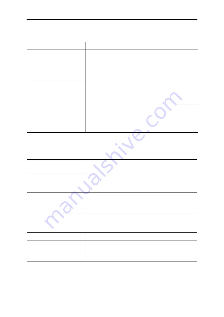
[ 1 ] Nothing appears on the LCD monitor.
Possible Causes
What to Check and Suggested Measures
(1) No power (neither main power
nor auxiliary control power)
supplied to the inverter.
Check the input voltage and interphase voltage unbalance.
Î
Turn ON a molded case circuit breaker (MCCB), a residual-current-
operated protective device (RCD)/earth leakage circuit breaker
(ELCB) (with overcurrent protection) or a magnetic contactor
(MC).
Î
Check for voltage drop, phase loss, poor connections, or poor
contacts and fix them if necessary.
Check whether the keypad is properly connected to the inverter.
Î
Remove the keypad, put it back, and see whether the problem
recurs.
Î
Replace the keypad with another one and check whether the
problem recurs.
(2) The keypad was not properly
connected to the inverter.
When running the inverter remotely, ensure that the extension cable is
securely connected both to the keypad and to the inverter.
Î
Disconnect the cable, reconnect it, and see whether the problem
recurs.
Î
Replace the keypad with another one and check whether the
problem per recurs.
[ 2 ] Connecting... display
Problem The “Connecting...” display does not change.
Possible Causes
What to Check and Suggested Measures
(1) The keypad is poorly connected. Check the remote operation extension cable conductance.
Î
Replace the remote operation extension cable conductance.
[ 3 ] “This inverter is not supported.” display
Problem “This inverter is not supported.” is displayed and the keypad turns ON and OFF repeatedly.
Possible Causes
What to Check and Suggested Measures
(1) The keypad and inverter are not
compatible.
Check the keypad and inverter compatibility.
Î
Connect a keypad that is compatible with the inverter.
[ 4 ] “USB Connected.” display
Problem “USB Connected.” is displayed and operation is not possible.
Possible Causes
What to Check and Suggested Measures
(1) A USB cable is connected to the
inverter.
The inverter has been set to USB communication mode by connecting it
to the computer via a USB cable.
Î
If not necessary to connect to the computer, disconnect the USB
cable.
Summary of Contents for FRENIC-AQUA series
Page 1: ...MEHT538b...
Page 2: ...User s Manual...
Page 13: ......
Page 15: ......
Page 33: ......
Page 35: ......
Page 61: ...2 26 Figure D Figure E NC No connection Do not make wiring NC NC...
Page 63: ...2 28 Figure J Figure K Charging lamp Charging lamp Viewed from A...
Page 83: ...2 48 Unit mm FRN45 to 55AQ1 4...
Page 84: ...2 9 External Dimensions 2 49 Chap 2 SPECIFICATIONS Unit mm FRN75 to 90AQ1 4...
Page 85: ...2 50 Unit mm FRN110AQ1S 4 FRN132AQ1S 4 FRN160AQ1S 4 FRN200AQ1S 4...
Page 87: ...2 52 Unit mm FRN500AQ1S 4 FRN630AQ1S 4 FRN710AQ1S 4...
Page 88: ...2 9 External Dimensions 2 53 Chap 2 SPECIFICATIONS 2 9 2 Keypad Unit mm Panel cutout...
Page 95: ......
Page 140: ...4 4 Options 4 33 Chap 4 SELECTING PERIPHERAL EQUIPMENT...
Page 279: ......
Page 281: ......
Page 341: ...6 60 Example of Thermal Overload Detection Characteristics...
Page 637: ......
Page 639: ......
Page 651: ...7 12 Figure 7 7 Terminal FM2 Output Selector...
Page 653: ......
Page 663: ......
Page 665: ......
Page 699: ......
Page 717: ......
Page 719: ......
Page 733: ......
Page 749: ......
Page 751: ...MEHT537 Phone 81 3 5435 7058 Fax 81 3 5435 7420 Printed in Japan 2012 08 H12b b12 CM00FOLS...


