546
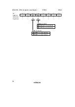
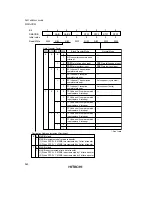
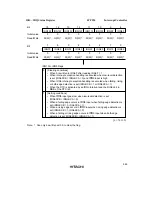
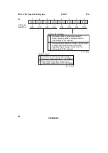
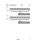
DTCER—DTC Enable Register
H'FF28 to H'FF2F
DTC
Bit
Initial value
Read/Write
7
DTCE7
0
R/W
6
DTCE6
0
R/W
5
DTCE5
0
R/W
4
DTCE4
0
R/W
3
DTCE3
0
R/W
2
DTCE2
0
R/W
1
DTCE1
0
R/W
0
DTCE0
0
R/W
0
DTC Activation Enable
1
Register
Bits
7
IRQ0
IRQ8
—
TGI2A
TGI5A
DMTEND0A
RXI2
—
Correspondence between Interrupt Sources and DTCER Register Bits
DTCERA
DTCERB
DTCERC
DTCERD
DTCERE
DTCERF
DTCERG
DTCERH
6
IRQ1
IRQ9
ADI
TGI2B
TGI5B
DMTEND0B
TXI2
—
5
IRQ2
IRQ10
TGI0A
TGI3A
—
DMTEND1A
RXI3
—
4
IRQ3
IRQ11
TGI0B
TGI3B
—
DMTEND1B
TXI3
—
3
IRQ4
IRQ12
TGI0C
TGI3C
CMIA0
RXI0
RXI4
—
2
IRQ5
IRQ13
TGI0D
TGI3D
CMIB0
TXI0
TXI4
—
1
IRQ6
IRQ14
TGI1A
TGI4A
CMIA1
RXI1
—
—
0
IRQ7
IRQ15
TGI1B
TGI4B
CMIB1
TXI1
—
—
DTC activation by interrupt is disabled
[Clearing conditions]
• When data transfer ends with the DISEL bit set to 1
• When the specified number of transfers end
DTC activation by this interrupt is enabled
[Hold condition]
When the DISEL bit is 0 and the specified number of
transfers have not ended
Note: For DTCE bit setting, bit manipulation instructions such as BSET and BCLR must be used
for reading and writing. For the initial setting only, however, when setting multiple
activation sources at one time, it is possible to disable interrupts and write to the relevant
register after a dummy read.
Summary of Contents for H8S/2670
Page 5: ......
Page 9: ......
Page 199: ...182 ...
Page 361: ...344 ...
Page 393: ...376 ...
Page 647: ...630 ...


