25
Pin No.
Type
Symbol
FP-144
I/O
Name and Function
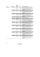
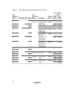
Watchdog timer
(WDT)
WDTOVF
37
Output
Watchdog timer overflow: Counter
overflow signal output pin in watchdog
timer mode.
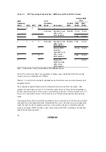
Serial communi-
cation interface
(SCI)/smart card
TxD2, TxD1,
TxD0/IrTxD
107, 138,
139
Output
Transmit data (channels 0, 1, 2): Data
output pins.
interface (SCI0
with IrDA function)
RxD2, RxD1,
RxD0/IrRxD
108, 135,
137
Input
Receive data (channels 0, 1, 2): Data
input pins.
SCK2, SCK1,
SCK0
109, 133,
134
Input/
output
Serial clock (channels 0, 1, 2): Clock
input/output pins.
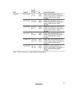
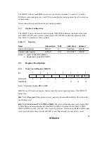
A/D converter
AN15 to
AN12,
AN7 to AN0
130 to 127,
126 to 123,
120 to 117
Input
Analog 15 to 12, 7 to 0: Analog input
pins.
ADTRG
110
Input
A/D conversion external trigger input:
Pin for input of an external trigger to
start A/D conversion.
D/A converter
DA3, DA2,
DA1, DA0
130, 129,
126, 125
Output
Analog output: D/A converter analog
output pins.
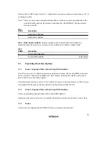
A/D converter,
D/A converter
AVCC
122
Input
The power supply pin for the A/D
converter and D/A converter.
When the A/D converter and D/A
converter are not used, this pin should
be connected to the system power
supply (+3 V).
AVSS
131
Input
The ground pin for the A/D converter
and D/A converter.
This pin should be connected to the
system power supply (0 V).
Vref
121
Input
The reference voltage input pin for the
A/D converter and D/A converter.
When the A/D converter and D/A
converter are not used, this pin should
be connected to the system power
supply (+3 V).
Summary of Contents for H8S/2670
Page 5: ......
Page 9: ......
Page 199: ...182 ...
Page 361: ...344 ...
Page 393: ...376 ...
Page 647: ...630 ...

