96
4.1.4
Register Configuration
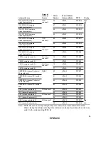
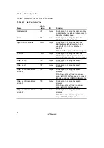
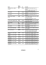
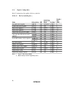
Table 4.2 summarizes the registers of the bus controller.
Table 4.2
Bus Controller Registers
Initial Value
Register
Size
Name
Abbreviation
R/W
Reset
Address
*
1
(Bits)
Bus width control register
ABWCR
R/W
H'FF/H'00
*
2
H'FEC0
8
Access state control register
ASTCR
R/W
H'FF
H'FEC1
8
Wait control register A
WTCRA
R/W
H'7777
H'FEC2
16
Wait control register B
WTCRB
R/W
H'7777
H'FEC4
16
Read strobe timing control register
RDNCR
R/W
H'00
H'FEC6
8
Chip select assertion period control
CSACRH
R/W
H'00
H'FEC8
8
registers
CSACRL
R/W
H'00
H'FEC9
8
Burst ROM interface control registers
BROMCRH
R/W
H'00
H'FECA
8
BROMCRL
R/W
H'00
H'FECB
8
Bus control register
BCR
R/W
H'1C00
H'FECC
16
DRAM control register
DRAMCR
R/W
H'0000
H'FED0
16
DRAM access control register
DRACCR
R/W
H'00
H'FED2
8
Refresh control register
REFCR
R/W
H'0000
H'FED4
16
Refresh timer counter
RTCNT
R/W
H'00
H'FED6
8
Refresh time constant register
RTCOR
R/W
H'FF
H'FED7
8
Notes: 1. Lower 16 bits of the address.
2. Determined by the MCU operating mode.
Summary of Contents for H8S/2670
Page 5: ......
Page 9: ......
Page 199: ...182 ...
Page 361: ...344 ...
Page 393: ...376 ...
Page 647: ...630 ...

