177
4.9.4
Transition Timing
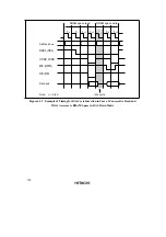
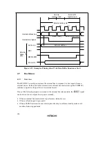
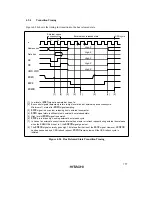
Figure 4.54 shows the timing for transition to the bus released state.
CPU cycle
External bus released state
External space
access cycle
T
1
T
2
ø
Address bus
HWR
,
LWR
BREQ
BACK
BREQO
High-Z
High-Z
High-Z
High-Z
High-Z
[1]
[2]
[3]
[7]
[4]
[5]
[6]
[8]
Data bus
AS
RD
[1] Low level of
BREQ
signal is sampled at rise of ø.
[2] Bus control signals temporarily return to high level at end of external space access cycle.
Minimum of 1 state after
BREQ
signal sampling.
[3]
BACK
signal is driven low, releasing bus to external bus master.
[4]
BREQ
signal state is still sampled in external bus released state.
[5] High level of
BREQ
signal is sampled.
[6]
BACK
pin is driven high, ending external bus release cycle.
[7] In case of an external access from an internal bus master or refresh request during external bus release
when the BREQOE bit is set to 1, the
BREQO
signal goes low.
[8] The
BREQO
signal normally goes high 1.5 states after the rise of the
BACK
signal. However, if
BREQO
has been asserted by a CBR refresh request,
BREQO
remains low until the CBR refresh cycle is
initiated.
Figure 4.54 Bus Released State Transition Timing
Summary of Contents for H8S/2670
Page 5: ......
Page 9: ......
Page 199: ...182 ...
Page 361: ...344 ...
Page 393: ...376 ...
Page 647: ...630 ...


