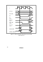
411
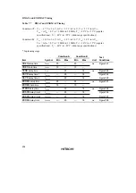
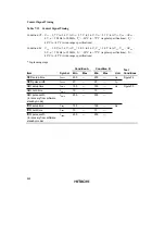
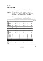
Condition A
Condition B
Test
Item
Symbol
Min
Max
Min
Max
Unit
Conditions
8-bit
timer
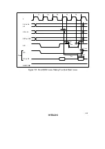
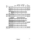
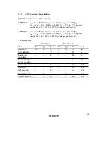
Timer output delay
time
t
TMOD
—
50
—
40
ns
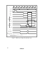
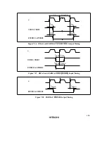
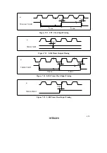
Figure7.33
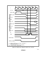
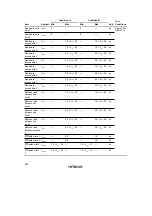
Timer reset input
setup time
t
TMRS
30
—
25
—
ns
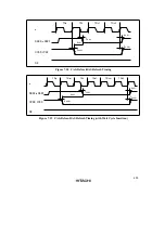
Figure7.35
Timer clock input
setup time
t
TMCS
30
—
25
—
ns
Figure7.34
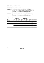
Timer
clock
Single-edge
specification
t
TMCWH
1.5
—
1.5
—
t
cyc
pulse
width
Both-edge
specification
t
TMCWL
2.5
—
2.5
—
t
cyc
WDT
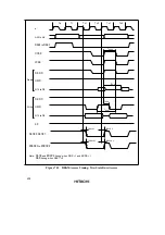
Overflow output delay
time
t
WOVD
—
50
—
40
ns
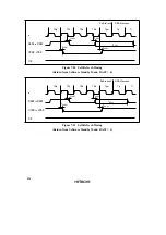
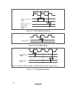
Figure7.36
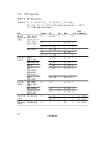
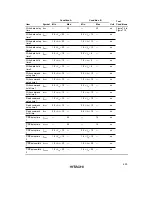
SCI
Input
clock
Asynchronous t
Scyc
4
—
4
—
t
cyc
Figure7.37
cycle
Synchronous
6
—
6
—
Input clock pulse
width
t
SCKW
0.4
0.6
0.4
0.6
t
Scyc
Input clock rise time
t
SCKr
—
1.5
—
1.5
t
cyc
Input clock fall time
t
SCKf
—
1.5
—
1.5
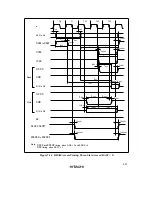
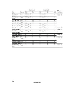
Transmit data delay
time
t
TXD
—
50
—
40
ns
Figure7.38
Receive data setup
time (synchronous)
t
RXS
50
—
40
—
ns
Receive data hold
time (synchronous)
t
RXH
50
—
40
—
ns
A/D
converter
Trigger input setup
time
t
TRGS
30
—
30
—
ns
Figure7.39
Summary of Contents for H8S/2670
Page 5: ......
Page 9: ......
Page 199: ...182 ...
Page 361: ...344 ...
Page 393: ...376 ...
Page 647: ...630 ...

