


109
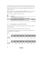
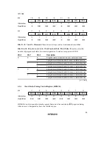
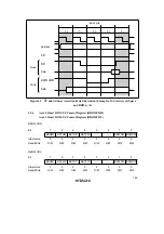
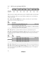
Bit 12—Column Address Output Cycle Number Select (CAST): Selects whether the column
address output cycle in DRAM access comprises 3 states or 2 states.
The setting of this bit applies to all areas designated as DRAM space.
Bit 12
CAST
Description
0
Column address output cycle comprises 2 states
(Initial value)
1
Column address output cycle comprises 3 states
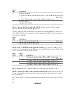
Bit 11—Reserved: This is a readable/writable bit, but the write value should always be 0.
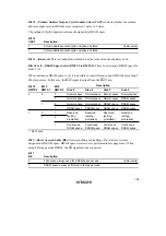
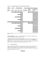
Bits 10 to 8—DRAM Space Select (RMTS2 to RMTS0): These bits designate DRAM space for
areas 2 to 5.
When continuous DRAM space is set, it is possible to connect large-capacity DRAM exceeding 2
Mbytes per area. In this case, the
RAS
signal is output from the
RAS2
pin.
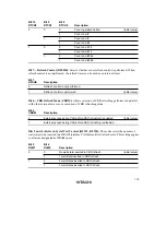
Bit 10
Bit 9
Bit 8
Description
RMTS2
RMTS 1
RMTS 0
Area 5
Area 4
Area 3
Area 2
0
0
0
Normal space
Normal space
Normal space
Normal space
1
Normal space
Normal space
Normal space
DRAM space
1
0
Normal space
Normal space
DRAM space
DRAM space
1
DRAM space
DRAM space
DRAM space
DRAM space
1
0
*
Reserved
Reserved
Reserved
Reserved
1
0
(setting
prohibited)
(setting
prohibited)
(setting
prohibited)
(setting
prohibited)
1
Continuous
DRAM space
Continuous
DRAM space
Continuous
DRAM space
Continuous
DRAM space
*
: Don’t care
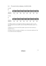
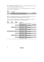
Bit 7—Burst Access Enable (BE): Selects enabling or disabling of burst access to areas
designated as DRAM space. DRAM space burst access is performed in fast page mode. When
using EDO page mode DRAM, the
OE
signal must be connected.
Bit 7
BE
Description
0
Full access always used for DRAM space access
(Initial value)
1
DRAM space access performed in fast page mode
Summary of Contents for H8S/2670
Page 5: ......
Page 9: ......
Page 199: ...182 ...
Page 361: ...344 ...
Page 393: ...376 ...
Page 647: ...630 ...