149
4.5.11
Byte Access Control
When DRAM with a
×
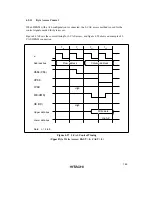
16 configuration is connected, the 2-CAS access method is used for the
control signals needed for byte access.
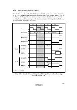
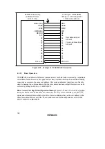
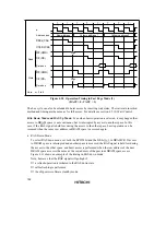
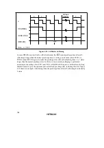
Figure 4.27 shows the control timing for 2-CAS access, and figure 4.28 shows an example of 2-
CAS DRAM connection.
T
p
High-Z
ø
RASn
(
CSn
)
UCAS
LCAS
WE
(
HWR
)
OE
(
RD
)
Upper data bus
Lower data bus
Address bus
T
r
T
c1
T
c2
Note: n = 2 to 5
Row address
Column address
Write data
High
High
Figure 4.27 2-CAS Control Timing
(Upper Byte Write Access: RAST = 0, CAST = 0)
Summary of Contents for H8S/2670
Page 5: ......
Page 9: ......
Page 199: ...182 ...
Page 361: ...344 ...
Page 393: ...376 ...
Page 647: ...630 ...


