599
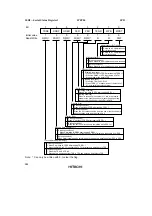
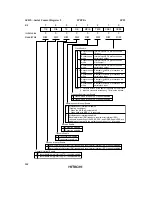
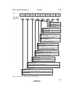
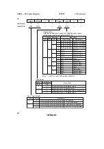
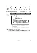
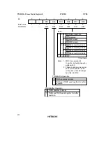
ADCSR—A/D Control/Status Register
H'FF98
A/D Converter
Bit
Initial value
Read/Write
7
ADF
0
R/W
*
6
ADIE
0
R/W
5
ADST
0
R/W
4
SCAN
0
R/W
3
CKS
0
R/W
2
CH2
0
R/W
1
CH1
0
R/W
0
CH0
0
R/W
Channel Select
Note: CH2, CH1, and CH0 are
used in combination with
bit 2 (CH3) in ADCR. See
ADCR—A/D Control
Register (H'FF99) for
details.
Clock Select
Note: CKS is used in combination with
bit 3 (CKS1) in ADCR. See
ADCR—A/D Control Register
(H'FF99) for details.
Scan Mode
0
Single mode
1
Scan mode
A/D Start
0
A/D conversion stopped
1
• Single mode: A/D conversion is started; cleared to 0
automatically when conversion ends
• Scan mode: A/D conversion is started, and continues
consecutively on the selected channels until ADST is
cleared to 0 by software, a reset, or a transition to
standby mode or module stop mode
A/D End Flag
0
[Clearing conditions]
• When 0 is written to ADF after reading ADF = 1
• When the DTC is activated by an ADF interrupt and ADDR is read
1
[Setting conditions]
• Single mode: When A/D conversion ends
• Scan mode: When A/D conversion ends on all specified channels
A/D Interrupt Enable
0
A/D conversion end interrupt request disabled
1
A/D conversion end interrupt request enabled
Note:
*
Can only be written with 0, to clear the flag.
Summary of Contents for H8S/2670
Page 5: ......
Page 9: ......
Page 199: ...182 ...
Page 361: ...344 ...
Page 393: ...376 ...
Page 647: ...630 ...


