SD20 series
329
Servo on
Rotation Detection
At speed reached
At position reached
At torque limit
Electromagnetic brake control
Overload prealarm
At speed limit
Position deviation too large
Output contact
Common-closed
X
Name
Function
0
S- RDY
Servo ready
1
SON-O
2
TGON
3
4
P- CMP
5
T-LT
6
7
BRAKE
8
S-LT
9
Servo alarm activated
10
OL-W
11
PER- W
Y
0
1
V- CMP
d
Reserved
d
-
12
Homing completed
HOME
ALM
Common-open
Two-parameter mode
...
...
...
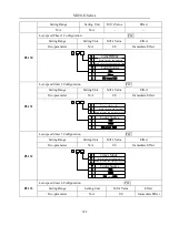
Fig 8.1.2 Setting programmable input terminal function
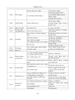
Function instruction of programmable output terminal:
Setting value
Function
Name
Instructions
0
Servo ready
S-RDY
S-RDY is activated when the servo drive is ready to run. All
fault and alarm conditions, if present, have been cleared.
1
Servo on
SON-O
SON-O is activated when the servo motor is ON.
2
Rotation Detection
TGON
When the absolute value of speed is higher than the value
of at rotation detection, TGON is activated.
3
At speed reached
V-CMP
V-CMP is activated when the servo motor has reached the
target rotation speed.
4
At position reached
P-CMP
Position completed
5
At torque limit
T-LT
T-LT is activated when toque is limited.
6
Servo alarm activated
ALM
ALM is activated when the drive has detected a fault condition.
7
Electromagnetic brake
control
BRAKE
BRAKE is activated actuation of motor brake.
8
Overload pre-alarm
OL-W
Overload pre-alarm signal
9
At speed limit
S-LT
S-LT is activated when speed is limited.
Summary of Contents for SD20-G Series
Page 35: ...SD20 G Series 35 M3 structure Fig 3 1 5 Servo drive structure 3...
Page 36: ...SD20 G Series 36 ML3 structure 118 5 5 7 5 93 297 8 223 118 93 0 5 12 5 7 5 4 M4...
Page 38: ...SD20 G Series 38 M4 structure Approx mass 10 365 kg Fig 3 1 7 Servo drive structure 5...
Page 39: ...SD20 G Series 39 M5 structure Approx msaa 11 1Kg Fig 3 1 8 Servo drive structure 6...
Page 40: ...SD20 G Series 40 M6 structure Approx mass 17 4Kg Fig 3 1 9 Servo drive structure 7...
Page 182: ...SD20 G Series 182 Fig 6 4 44SD20E Cam internal frameworkdiagram...


