SD20-G Series
159
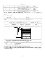
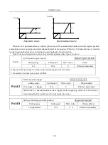
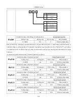
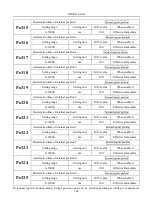
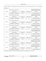
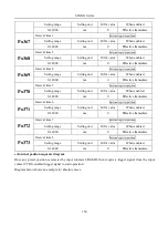
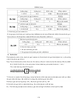
(2) Setting parameters
Parameters
Remarks
Po308
b □□0□
Command pulse clear function is OFF.
b □□1□
Command pulse clear function is ON.
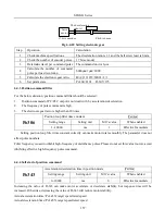
6.4.7 Frequency-division output function
Encoder pulse is frequency-division processed by servo drive internal circuit, and orthogonal differential
signal will output. The frequency-division signal setting is as below:
PULSE
SIGN
Position
command
PA0+36
PA0 -
PULS
35
15
PB0+
44
34
PB0- 33
PZ0+ 16
/PULS
SIGN
PZ0-
12
17
27 /SIGN
43 PL2
28
PL1
GND
GND 40
HPULS
HSIGN
GND
High-speed pulse
position command
3
4 HPULS+
6
5
HPULS-
HSIGN+
HSIGN-
24 GND
Pulse output
Po018
Internal position
given
Motor shaft
Position
command
Frequency-
division
output
OZ
CM
37
30
DC:5V- 24V
R
Collector pulse
High-speed
counter
3
4
2
1
0
5
High-speed
counter 1
High-speed
counter 2
Fig 6.4.21 Frequency-division output diagram
(1)
Output signal
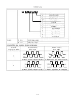
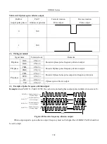
Encoder pulse frequency-division signal has two output modes, one kind outputs PAO, PBO, PZO differential
signal.
Signal name
Terminal code
Remarks
PA phase
PAO-
CN3 – 36
Encoder A phase pulse frequency-division output
PAO+
CN3 – 35
PB phase
PBO-
CN3 – 34
Encoder B phase pulse frequency-division output
Summary of Contents for SD20-G Series
Page 35: ...SD20 G Series 35 M3 structure Fig 3 1 5 Servo drive structure 3...
Page 36: ...SD20 G Series 36 ML3 structure 118 5 5 7 5 93 297 8 223 118 93 0 5 12 5 7 5 4 M4...
Page 38: ...SD20 G Series 38 M4 structure Approx mass 10 365 kg Fig 3 1 7 Servo drive structure 5...
Page 39: ...SD20 G Series 39 M5 structure Approx msaa 11 1Kg Fig 3 1 8 Servo drive structure 6...
Page 40: ...SD20 G Series 40 M6 structure Approx mass 17 4Kg Fig 3 1 9 Servo drive structure 7...
Page 182: ...SD20 G Series 182 Fig 6 4 44SD20E Cam internal frameworkdiagram...

