SD20-G Series
104
OFF
OFF
ON
ON
T1
OFF
OFF
OFF
ON
OFF
OFF
ON
OFF
300ms
100ms
Delay time
Delay time
Servo and motor
enable status
Electromagnetic
braking signal
Enable
signal
Braking status
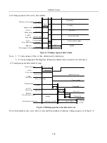
Fig 6-1-4 Electromagnetic brake sequence diagram
Note: after servo enabled is off, T1 is the lower value of So-03 and the time taken by speed arriving to setting
value of So-16.
c)
Power-off brake function
When power-off is detected, make motor in lock state to prevent equipment from falling off.
So-28
Power-off brake
Speed Position Torque
Setting range
Setting unit
Mfr’s value
Effect
0
~
1
N/A
1
Effective Immediate
0:invalid 1:valid
So-29
Power-off brake time
Speed Position Torque
Setting range
Setting unit
Mfr’s value
Effect
500
~
30000
0.1ms
1000
Effective Immediate
Power-off brake function
Brake DO status
Off
ON
Off
Off
Locked
Unlock brake
So- 29
Internl circuit postpones lock
Off
Off
ON
ON
Power supply
Fig 6-1-5 Powewr-off brake sequence diagram
Summary of Contents for SD20-G Series
Page 35: ...SD20 G Series 35 M3 structure Fig 3 1 5 Servo drive structure 3...
Page 36: ...SD20 G Series 36 ML3 structure 118 5 5 7 5 93 297 8 223 118 93 0 5 12 5 7 5 4 M4...
Page 38: ...SD20 G Series 38 M4 structure Approx mass 10 365 kg Fig 3 1 7 Servo drive structure 5...
Page 39: ...SD20 G Series 39 M5 structure Approx msaa 11 1Kg Fig 3 1 8 Servo drive structure 6...
Page 40: ...SD20 G Series 40 M6 structure Approx mass 17 4Kg Fig 3 1 9 Servo drive structure 7...
Page 182: ...SD20 G Series 182 Fig 6 4 44SD20E Cam internal frameworkdiagram...


