SD20-G Series
155
Step
Operation
Description
1
Check machine specifications.
Check the reduction ratio, ball screw lead, and pulley
diameter.
2
Check the encoder resolution of servo
motor.
Check the number of encoder pulse for one revolution.
3
Travel per command pulse
Determine the travel per command pulse from the
command controller
4
Calculate the number of command pulse
per load shaft revolution
Calculate the number of command pulse for turning load
shaft one revolution based on the previously determined
command unit.
5
Calculate the electronic gear ratio.
Use the electronic gear ratio equation to calculate the ratio
6
Set parameters.
Set parameters using the calculated values.
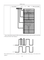
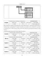
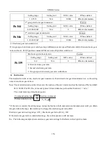
Setting parameters procedure is as below:
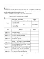
Electric gear ratio
selection
Electric gear
ratio 1
1. Electric gear ratio 1
2. Electric ger ratio 2
3. Terminal selection
Electric gear
ratio 2
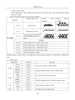
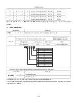
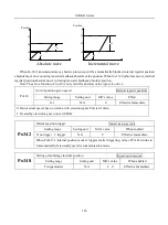
When Po304 and Po346 are not 0, electronic gear ratio equals to Po304/Po305 (Po344/Po346). If Po304
(Po344)=0, pulse numbers of motor rotating a rotation is controlled by Po305 (Po304).
3)
Related parameters
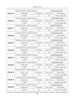
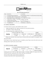
It needs 131072 pulses from servo drive to make a 17bit encoder rotate a rotation (when electronic gear is 1).
①
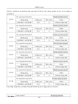
Function code
Po304
1
st
group electronic gear numerator
Position
Setting range
Setting unit
Mfr’s value
When enabled
0~65535
N/A
0
Effective Immediate
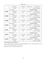
Po305
1
st
electronic gear denominator
Position
Summary of Contents for SD20-G Series
Page 35: ...SD20 G Series 35 M3 structure Fig 3 1 5 Servo drive structure 3...
Page 36: ...SD20 G Series 36 ML3 structure 118 5 5 7 5 93 297 8 223 118 93 0 5 12 5 7 5 4 M4...
Page 38: ...SD20 G Series 38 M4 structure Approx mass 10 365 kg Fig 3 1 7 Servo drive structure 5...
Page 39: ...SD20 G Series 39 M5 structure Approx msaa 11 1Kg Fig 3 1 8 Servo drive structure 6...
Page 40: ...SD20 G Series 40 M6 structure Approx mass 17 4Kg Fig 3 1 9 Servo drive structure 7...
Page 182: ...SD20 G Series 182 Fig 6 4 44SD20E Cam internal frameworkdiagram...

