SD20-G Series
180
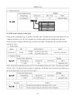
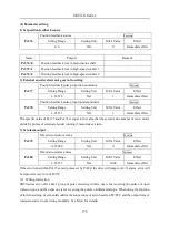
1) Position feedback source setting
Po382
Gantry position feedback source
Position
Setting Range
Setting Unit
Mfr’s value
Effect
0~1
N/A
0
Immediate effect
0
:
high-speed counter 1;
1
:
high-speed counter 2;
2) Feedback ratio setting
Po384
Gantry synchron feedback proportion numerator
Position
Setting Range
Setting Unit
Mfr’s value
Effect
1~2147483647
N/A
10
Immediate effect
Po386
Gantry synchron feedback proportion denominator
Position
Setting Range
Setting Unit
Mfr’s value
Effect
1~2147483647
N/A
10
Immediate effect
3) Gain setting
Po381
Gantry synchron gain
Position
Setting Range
Setting Unit
Mfr’s value
Effect
1~30000
N/A
1
Immediate effect
The value of Po381 cannot be higher than the value of position-loop gain Po301.
4) Alarm output setting
Po383
Gantry synchron alarm pulse
Position
Setting Range
Setting Unit
Mfr’s value
Effect
10~65535
N/A
1000
Immediate effect
Alarm AL-32 given when synchro error is higher than Po383.
(3)
Wiring Instruction
Gantry synchron needs interactive connection of two servo drives, which means that frequency dividing
output of shaft A is connected to pulse input of shaft B, and frequency dividing output of shaft B is
connected to the pulse input of shaft A. Typical wiring diagram shows as below:
Summary of Contents for SD20-G Series
Page 35: ...SD20 G Series 35 M3 structure Fig 3 1 5 Servo drive structure 3...
Page 36: ...SD20 G Series 36 ML3 structure 118 5 5 7 5 93 297 8 223 118 93 0 5 12 5 7 5 4 M4...
Page 38: ...SD20 G Series 38 M4 structure Approx mass 10 365 kg Fig 3 1 7 Servo drive structure 5...
Page 39: ...SD20 G Series 39 M5 structure Approx msaa 11 1Kg Fig 3 1 8 Servo drive structure 6...
Page 40: ...SD20 G Series 40 M6 structure Approx mass 17 4Kg Fig 3 1 9 Servo drive structure 7...
Page 182: ...SD20 G Series 182 Fig 6 4 44SD20E Cam internal frameworkdiagram...


