SD20-G Series
210
6.6.10 Cogging torque compensation
Cogging torque is generated between permanent magnet and stator core when servo motor is not power
ed on. Cogging torque will make motor have vibration and noise. SD20 series drive reduce the
influence of cogging torque through software and improve torque performance of servo motor.
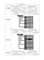
So-25
Electric angle identification
Speed Position Torque
Setting range
Setting unit
Mfr’s value
Effect
0~10
N/A
0
Effective Immediate
When So-25=9, cogging torque compensation study is enabled,servo motor shaft must be in
no load status.
Note
:
In cogging torque study process, servo drive will display TEST for 1-2 minutes, don’t
touch motor shaft during the time.
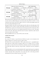
Po289
Cogging torque compensation
Speed Position Torque
Setting range
Setting unit
Mfr’s value
Effect
0~1
N/A
0
Re-power on
0: invalid 1.: vaild
6.6.11 Friction torque compensation
Friction in servo motor can affect response accuracy, rotation smoothness, even cause motor oscillation.
SD20 servo drive can set friction torque compensation by software. Sevo drive has three compensation
points, linear interpolation is used to compensate between the points. The operation step is as below:
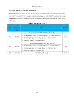
1, Confirm motor rated speed
2.According to actual motor speed, set Po290, Po 292,Po294.
Note: Po290, Po 292,Po294.is percentage of motor speed in study state to rated speed.
Po290, Po 292,Po294 corresponds to motor low speed stage, medium speed range and high speed stage
separately.
3.Set So-25=10, So-14 enter study mode, servo drive start to study.
4.After step3 is completed, friction torque compensation study is finished.
Note :
i)
SD20 servo drive internal 3 points must be used together, or compensation accuracy is not good.
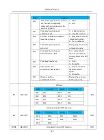
ii) In study of friction torque compensation process, percentage of motor torque in study state to rated
torque is recorded in Po291,Po293, Po295. If user need input it manually, the percentage can be got by
two methods:
Check output torque by PC/PLC.
Check Lo-20 value, which is percentage of motor torque in study state to rated torque.
Summary of Contents for SD20-G Series
Page 35: ...SD20 G Series 35 M3 structure Fig 3 1 5 Servo drive structure 3...
Page 36: ...SD20 G Series 36 ML3 structure 118 5 5 7 5 93 297 8 223 118 93 0 5 12 5 7 5 4 M4...
Page 38: ...SD20 G Series 38 M4 structure Approx mass 10 365 kg Fig 3 1 7 Servo drive structure 5...
Page 39: ...SD20 G Series 39 M5 structure Approx msaa 11 1Kg Fig 3 1 8 Servo drive structure 6...
Page 40: ...SD20 G Series 40 M6 structure Approx mass 17 4Kg Fig 3 1 9 Servo drive structure 7...
Page 182: ...SD20 G Series 182 Fig 6 4 44SD20E Cam internal frameworkdiagram...


