SD20-G Series
52
4.1.2 Main circuit terminal wiring
(1) Wiring size
The following are applicable wire sizes:
Single wire: Ø 0.5~ Ø 1.6mm
;
Braided wire: 0.8 mm
2
~3.5mm
2
(American standard AWG28~AWG12)
(2) Connection procedure
1 Strip the end of the wire about 5~6mm.
2 Use a supplied lever or a standard flat-blade screwdriver (blade width of 3.0 to 3.5 mm). Put them into the
slot, and press down firmly to open the wire terminal.
3 Insert the wire core into the opening and then close the opening by releasing the lever or removing the
screwdriver.
Press down firmly
Press down firmly
Fig 4.1.3 Connection procedure
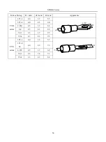
When using screw terminal for wiring, if lug is needed, dimension of screw terminal as below:
Summary of Contents for SD20-G Series
Page 35: ...SD20 G Series 35 M3 structure Fig 3 1 5 Servo drive structure 3...
Page 36: ...SD20 G Series 36 ML3 structure 118 5 5 7 5 93 297 8 223 118 93 0 5 12 5 7 5 4 M4...
Page 38: ...SD20 G Series 38 M4 structure Approx mass 10 365 kg Fig 3 1 7 Servo drive structure 5...
Page 39: ...SD20 G Series 39 M5 structure Approx msaa 11 1Kg Fig 3 1 8 Servo drive structure 6...
Page 40: ...SD20 G Series 40 M6 structure Approx mass 17 4Kg Fig 3 1 9 Servo drive structure 7...
Page 182: ...SD20 G Series 182 Fig 6 4 44SD20E Cam internal frameworkdiagram...


