SD20-G Series
143
/ PULS
CN3-15
2
)
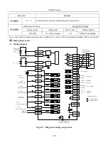
Internal register position pulse mode
a)
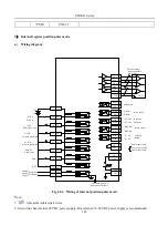
Wiring diagram
DI1
DI2
DI3
DI4
DI5
DI6
38
DI 7
39
GP
2
18
19
20
21
22
DI8-
14
12V
|
24V
At speed
limited
/ SON-I
F- INH
/ ESP
R- INH
/AL-RST
Alarm reset
SD0
Encoder output
pulse applicable
line receiver
Servo alarm
Servo ready
Rotation
detection
Brake output
Photocoupler limit
Max voltage:30 VDC
Max current:
50mA
The shielding wire is
connected to the shell
.
Servo on
Emergency stop
Forward prohibited
Reverse prohibited
DI8+
13
High-speed
DI channel
PA0+ 36
PA0- 35
PB0 + 34
PB0 - 33
PZ0 + 16
PZ0- 17
GND
AGND 40
11
26
41
42
9
10
ALM+ 7
ALM- 8
D 04+ 32
0Z
31
D02 +
D 03+
D 02-
D03-
D 01+
D 01-
D04 -
37
CM
30
1
GND
40
+24V 29
CM
30
+ 24V
/ S- RDY+
/ S- RDY-
/ TGON+
/ TGON-
/ BRAKE +
/
/ S- LT+
/ S- LT-
AO
BRAKE -
Internal
position
trigger
SD1
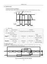
Fig 6.4.6 Wiring of internal position pulse mode
Note:
1. represents twisted-pair wires.
2 .Servo drive has internal 24 VDC power supply. But external 12~24VDC power supply is recommended.
Summary of Contents for SD20-G Series
Page 35: ...SD20 G Series 35 M3 structure Fig 3 1 5 Servo drive structure 3...
Page 36: ...SD20 G Series 36 ML3 structure 118 5 5 7 5 93 297 8 223 118 93 0 5 12 5 7 5 4 M4...
Page 38: ...SD20 G Series 38 M4 structure Approx mass 10 365 kg Fig 3 1 7 Servo drive structure 5...
Page 39: ...SD20 G Series 39 M5 structure Approx msaa 11 1Kg Fig 3 1 8 Servo drive structure 6...
Page 40: ...SD20 G Series 40 M6 structure Approx mass 17 4Kg Fig 3 1 9 Servo drive structure 7...
Page 182: ...SD20 G Series 182 Fig 6 4 44SD20E Cam internal frameworkdiagram...


