SD20-G Series
71
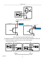
DC24V
Servo drive
Command controller
Fig 4-3-15 Relay output interface circuit
9 DO1+
10 DO1-
External 0V
External 5V- 24 V dc
Relay is not
connected.
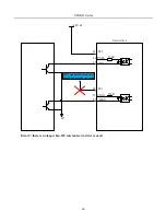
Servo drive
9 DO1+
10 DO1-
0V
External 5V- 24 V dc
Wrong direction of
flyback diode
Servo drive
External
Fig 4-3-16 Wrong wirng of relay output interface circuit
3)
Note
:
Relay is inductance load, please connect a freewheel diode in antiparallel between the load.
If the freewheel diode is connected inversely, servo drives will be damaged.
(2) Photocoupler isolating output
24 VDC
.
3.3K
Servo drive
Command controller
24 VDC
3.3K
.
Servo drive
Command controller
PNP type NPN type
Fig 4-3-17 Photocoupler output interface circuit
Note:
Summary of Contents for SD20-G Series
Page 35: ...SD20 G Series 35 M3 structure Fig 3 1 5 Servo drive structure 3...
Page 36: ...SD20 G Series 36 ML3 structure 118 5 5 7 5 93 297 8 223 118 93 0 5 12 5 7 5 4 M4...
Page 38: ...SD20 G Series 38 M4 structure Approx mass 10 365 kg Fig 3 1 7 Servo drive structure 5...
Page 39: ...SD20 G Series 39 M5 structure Approx msaa 11 1Kg Fig 3 1 8 Servo drive structure 6...
Page 40: ...SD20 G Series 40 M6 structure Approx mass 17 4Kg Fig 3 1 9 Servo drive structure 7...
Page 182: ...SD20 G Series 182 Fig 6 4 44SD20E Cam internal frameworkdiagram...

