


SD20-G Series
67
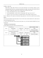
Servo drive
44
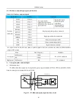
43 PL2
PULS
150R
15 /PULS
12
28 PL1
SIGN
150R
27 /SIGN
29 +24V
30 CM
Connect this terminal to
No. 30 pin.
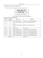
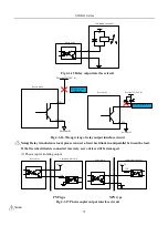
2)
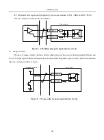
High-speed pulse command input
High-speed command pulse can be output to servo drive by differential drive.
GND
GND
4
3
HPULS+
HPULS-
5
6
HSIGN+
HSIGN -
24
Upper device
Servo drive
Fig 4.3.10 High-speed differential signal
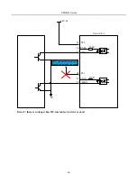
Please make sure differential input voltage is 5V, otherwise servo drive receives pulse unsteadily or servo
drive internal device will be damaged.
Please make sure the 5V power grounding is connected to GND, otherwise the following situation will
Summary of Contents for SD20-G Series
Page 35: ...SD20 G Series 35 M3 structure Fig 3 1 5 Servo drive structure 3...
Page 36: ...SD20 G Series 36 ML3 structure 118 5 5 7 5 93 297 8 223 118 93 0 5 12 5 7 5 4 M4...
Page 38: ...SD20 G Series 38 M4 structure Approx mass 10 365 kg Fig 3 1 7 Servo drive structure 5...
Page 39: ...SD20 G Series 39 M5 structure Approx msaa 11 1Kg Fig 3 1 8 Servo drive structure 6...
Page 40: ...SD20 G Series 40 M6 structure Approx mass 17 4Kg Fig 3 1 9 Servo drive structure 7...
Page 182: ...SD20 G Series 182 Fig 6 4 44SD20E Cam internal frameworkdiagram...