SD20-G Series
72
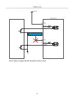
1. Match usage of power supply and current-limiting resistor make external photocoupler on state.
2.Max allowable voltage and max current capacity of internal photocoupler output circuit is as below:
Voltage: DC 30V (Max)
Current: DC 50mA (Max)
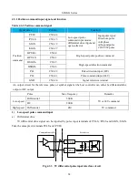
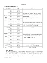
4.3.5 Encoder frequency-division output signal and function
Signal name
Pin No.
Function
Common
output
terminal
PAO+
CN3-36
Encoder A phase pulse frequency-division output
PAO-
CN3-35
PBO+
CN3-34
Encoder B phase pulse frequency-division output
PBO-
CN3-33
PZO+
CN3-16
Encoder Z phase pulse frequency-division output
PZO-
CN3-17
OZ
CN3-37
Encoder Z-phase pulse outputs open collector signal
CM
CN3-30
Reference terminal
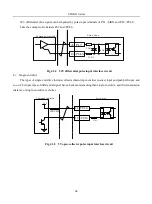
Frequency-division circuit in the servodrive processes encoder input signal by the mode of frequency-division,
which is output by differential bus mode. Interface circuit includes high-speed photocoupler interface and
differential chip interface. Take the example of encoder A phase pulse frequency-division output.
Servo drive
High-speed photocoupler
PAO 36
35
/PAO
Controller
Fig 4-3-18 Photocoupler interface circuit
Summary of Contents for SD20-G Series
Page 35: ...SD20 G Series 35 M3 structure Fig 3 1 5 Servo drive structure 3...
Page 36: ...SD20 G Series 36 ML3 structure 118 5 5 7 5 93 297 8 223 118 93 0 5 12 5 7 5 4 M4...
Page 38: ...SD20 G Series 38 M4 structure Approx mass 10 365 kg Fig 3 1 7 Servo drive structure 5...
Page 39: ...SD20 G Series 39 M5 structure Approx msaa 11 1Kg Fig 3 1 8 Servo drive structure 6...
Page 40: ...SD20 G Series 40 M6 structure Approx mass 17 4Kg Fig 3 1 9 Servo drive structure 7...
Page 182: ...SD20 G Series 182 Fig 6 4 44SD20E Cam internal frameworkdiagram...


