


SD20-G Series
144
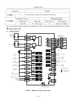
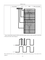
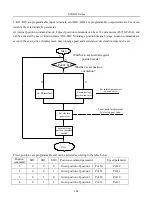
3. DI1~DI8 are programmable input terminals, and DO1~DO4 are programmable output terminals. Users can
redefine these terminals by parameter.
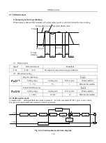
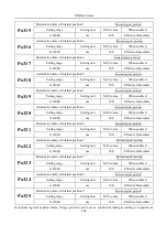
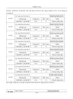
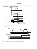
At internal position command mode, 8 preset position commands can be set by parameters (Po350-Po364), and
can be activated by use of input contacts SD0~SD2. Multistage position means 8-stage postion commands are
saved in the servo drive, displacement, max running speed and acceleration/deceleration time can be set.
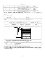
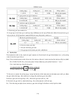
Preset positions are programmable and can be selected according to the table below:
Position
command
SD2
SD1
SD0
Position command parameter
Speed parameter
1
0
0
0
Given postion of postion 1
Po350
Po330
2
0
0
1
Given postion of postion 2
Po352
Po331
3
0
1
0
Given postion of postion 3
Po354
Po332
4
0
1
1
Given postion of postion 4
Po356
Po333
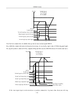
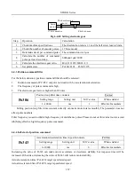
Start
Set multi-stage
position run curve
Set electric
gear ratio
Set multi-stage
position command
enabled.
Over
Set related parameters
of each curve.
To set motor displacment
by electric gear ratio.
Po001.X=5
Whether to set internal register
position mode?
Whether to set position
circulation?
Y
N
N
Y
Set DI terminal
Summary of Contents for SD20-G Series
Page 35: ...SD20 G Series 35 M3 structure Fig 3 1 5 Servo drive structure 3...
Page 36: ...SD20 G Series 36 ML3 structure 118 5 5 7 5 93 297 8 223 118 93 0 5 12 5 7 5 4 M4...
Page 38: ...SD20 G Series 38 M4 structure Approx mass 10 365 kg Fig 3 1 7 Servo drive structure 5...
Page 39: ...SD20 G Series 39 M5 structure Approx msaa 11 1Kg Fig 3 1 8 Servo drive structure 6...
Page 40: ...SD20 G Series 40 M6 structure Approx mass 17 4Kg Fig 3 1 9 Servo drive structure 7...
Page 182: ...SD20 G Series 182 Fig 6 4 44SD20E Cam internal frameworkdiagram...