SD20-G Series
131
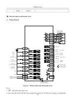
Note:
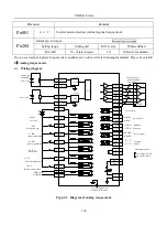
1 represents twisted-pair wires.
2 Servo drive has internal 24 VDC power supply. But external 12~24VDC power supply is recommended.
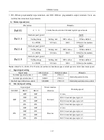
3 DI1~DI8 are programmable input terminals, and DO1~DO4 are programmable output terminals. Users can
redefine these terminals by parameter.
b)
Related parameters
Parameter
Remarks
Po001
d □ 4
Control mode selection: analog torque mode.
(
1
)
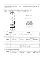
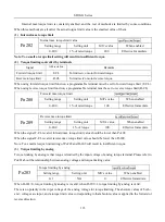
Analog torque command source
Po429
Analog torque command source
Speed Torque
Position
Setting range
Setting unit
Mfr’s value
When enabled
0~1
N/A
1
Effective Immediate
Setting value
Constent
0
Analog command is set by AI1.
1
Analog command is set by AI2.
(
2
)
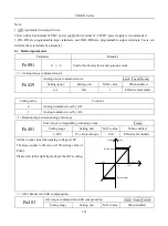
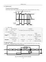
Relationship between analog and torque
Po401
Max torque corresponding to Analog torque
Torque
Setting range
Setting unit
Mfr’s value
When enabled
1~800
1% of rated torque
100
Effective Immediate
Set the torque value when analog voltage is 10V.
The slope equals to the ratio of 10V/setting value of
Po401.
Please refer to the right figure about the mfr’s setting:
10V
-10V
Voltage (V)
Torque N·m
0
Rated torque
Rated torque
(
3
)
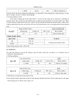
AI2 channel zero drift compensation
Po403
AI2 torque command zero drift compensation
Speed Torque
Position
Setting range
Setting unit
Mfr’s value
When enabled
Summary of Contents for SD20-G Series
Page 35: ...SD20 G Series 35 M3 structure Fig 3 1 5 Servo drive structure 3...
Page 36: ...SD20 G Series 36 ML3 structure 118 5 5 7 5 93 297 8 223 118 93 0 5 12 5 7 5 4 M4...
Page 38: ...SD20 G Series 38 M4 structure Approx mass 10 365 kg Fig 3 1 7 Servo drive structure 5...
Page 39: ...SD20 G Series 39 M5 structure Approx msaa 11 1Kg Fig 3 1 8 Servo drive structure 6...
Page 40: ...SD20 G Series 40 M6 structure Approx mass 17 4Kg Fig 3 1 9 Servo drive structure 7...
Page 182: ...SD20 G Series 182 Fig 6 4 44SD20E Cam internal frameworkdiagram...

