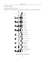
SD20-G Series
87
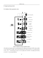
5.2 Keypad operating procedure
5.2.1 Switchover between parameter section
Power on
Status Display Mode
Auxiliary
fun ction
Monitor Mode
Main function
section
Press MODE key
MODE
MODE
MODE
MODE
Press MODE key
Press MODE key
Fault display
MODE
Motor parameter section
MODE
MODE
Built-in PLC parameter
and CAM area
Press MODE key
Press MODE key
Press MODE key
Press MODE key
Fig 5-2-1 Switchover between parameter section
After main circuit is powered on, servo status display So-09 is displayed in the keypad, the Mfr’s value of which
is servo output speed. The display content will switch among monitor function section (Lo-□□), auxiliary function
section
(
So-□□
)
, main function section (Po□□□), motor parameters section (Ho□□□) and high-speed counting
section (PL□□□) by pressing MODE key.
Summary of Contents for SD20-G Series
Page 35: ...SD20 G Series 35 M3 structure Fig 3 1 5 Servo drive structure 3...
Page 36: ...SD20 G Series 36 ML3 structure 118 5 5 7 5 93 297 8 223 118 93 0 5 12 5 7 5 4 M4...
Page 38: ...SD20 G Series 38 M4 structure Approx mass 10 365 kg Fig 3 1 7 Servo drive structure 5...
Page 39: ...SD20 G Series 39 M5 structure Approx msaa 11 1Kg Fig 3 1 8 Servo drive structure 6...
Page 40: ...SD20 G Series 40 M6 structure Approx mass 17 4Kg Fig 3 1 9 Servo drive structure 7...
Page 182: ...SD20 G Series 182 Fig 6 4 44SD20E Cam internal frameworkdiagram...


