background image

SD20-G Series 

157 


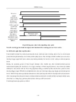
Servo 

motor

17 bits encoder

The deceleration 

ratio is 1

Pitch is 6mm.


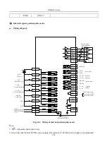
Fig 6-4-18 Setting electronic gear 

Step 

Operation 

Calculation   

Check machine specifications.   

The deceleration ratio is 1:1 and the ball screw lead is 6mm. 

Check the number of encoder pulses. 

17 bits encoder 

Determine travel per command pulse 

The command unit is 1μm. 

Calculate  the  number  of  command 
pulse per load revolution 

6000μm/1μm=6000   

Calculate the electronic gear ratio. 

B/A=(131072/6000) ×1/1 

Set parameters. 

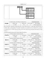
Po304=8192      Po305=375 

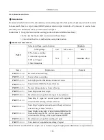
6.4.3 Position command filter 

For the below situation, position command filter should be selected:   

1.


Position command of PC/PLC output is not dealt with by acceleration/deceleration. 

2.


The frequency of pulse command is high. 

3.


The electronic gear ratio is higher than 10 times. 

Po306


Position loop filter time constant                                                                       

Position


Setting range 

Setting unit 

Mfr’s value 

When enabled 

1~10000 

ms 

Effective Immediate 

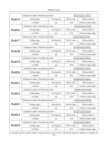
Setting position loop filter time constant correctly can make motor rotate smoothly. The parameter does not 

affect pulse numbers. 

Filter frequency is used to inhibit high-frequency of disturbance pulses. Please do not set this value too low, avoid 

inhibiting effective high-frequency pulse command. 


6.4.4 Soft start of position command 

Po343 

Acceleration/deceleration time in position mode                                   

Position


Setting range 

Setting unit 

Mfr’s value 

When enabled 

0~10000 

ms 

Effective Immediate 

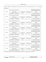
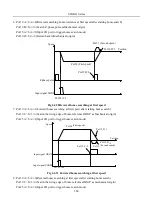
Increasing  the  value  of  Po343  can  make  motor  accelerate  or  decelerate  stability,  but  response  time  will  be 

increased. Otherwise, decreasing the value of Po343 will reduce motor stability. 

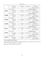
Actual acceleration time=Po343 X target speed/rated speed 

Actual deceleration time=Po345 X target speed/rated speed 

Summary of Contents for SD20-G Series

Page 1: ...r internal register position mode S speed mode Sr internal register speed mode Sz analog speed mode T torque mode Tr internal register torque mode Tz analog torque mode 2 Usage of backslash Backslash...

Page 2: ...LLATION 32 3 1 SERVO DRIVES INSTALLATION 32 3 1 1 INSTALLATION CONDITIONS 32 3 1 2 INSTALLATION PROCEDURE AND MINIMUM CLEARANCES 33 3 1 3 SERVO DRIVE DIMENSION 34 3 2 SERVO MOTOR INSTALLATION 39 3 2 1...

Page 3: ...ING 79 4 4 2 POWER CABLE OF SERVO DRIVE AND SERVO MOTOR 82 4 5 EMC 83 4 5 1 DEFINITION 83 4 5 2 INSTALLATION ENVIORNMENT 83 4 5 3 SELECTION AND INSTALLATION OF PERIPHERAL EMC DEVICES 84 4 5 4 SHIELDED...

Page 4: ...7 6 4 5 POSITION COMMAND INHIBIT FUNCTION 158 6 4 6 COMMAND PULSE CLEAR FUNCTION 158 6 4 7 FREQUENCY DIVISION OUTPUT FUNCTION 159 6 4 8 HOMESEARCHMODE 163 6 4 9MECHANICAL ORIGIN SEARCH FUNCTION 169 6...

Page 5: ...ONTROL 208 6 6 9 DI TERMINALS FILTER FUNCTION 208 6 6 10 OTHER OUTPUT SIGNALS 210 6 6 11 FRICTION TORQUE COMPENSATION 208 6 6 12 GRAVITY TORQUE COMPENSATION 209 6 6 13 INPUT POWER PHASE LOSS PROTECTIO...

Page 6: ...FUNCTION 266 7 4 2 LOW FREQUENCY VIBRATION INHIBITION FUNCTION 267 VIII LIST OF PARAMETERS 268 8 1 1 MONITOR FUNCTION GROUP LO 268 8 1 2 UTILITY FUNCTION GROUP SO 271 8 1 3 MAIN FUNCTION GROUP PO 279...

Page 7: ...1 3 PARAMETER RELATED TO COMMUNICATION 344 XI APPENDIX 346 11 1 ENCODER CABLE SELECTION 346 11 1 1 ABSOLUTE ENCODER CABLE 346 11 1 2 INCREMENTAL ENCODER CABLE 347 11 1 3 RESOLVER ENCODER CABLE 348 11...

Page 8: ...l operation precisely as described in this manual Do not remove the front cover cables connectors or optional items while the power is ON Do not damaged press exert excessive force or place heavy obje...

Page 9: ...ect to exposure to water oil or chemicals 7 Locations subject to shock or vibration Do not hold the product by the cables or motor shaft while transporting it Do not place any load exceeding the limit...

Page 10: ...iate and sufficient countermeasures for each form of potential interference when installing systems in the following locations Locations subjects to static electricity or other forms of noise Location...

Page 11: ...e B3 B3 B1 B1 B1 B1 B1 B1 B1 B3 3 phase No built in braking resistor D52 D70 D71 4 core 23 bit incremental encoder 4 core 17 bit absolute encoder 4 core 23 bit absolute encoder 101 No built in braking...

Page 12: ...ight on Main circuit power input terminal AC input terminal of main circuit power supply Refer to 4 1 Main circuit wiring Control power input terminal AC input terminal of control power supply Refer t...

Page 13: ...Hz Braking type External braking resistor Built in braking resistor b 380V 400V servo drive Name M2 M3 MM4 M4 M5 M6 Servo drive SD20 G 102 152 202 302 452 552 752 113 153 183 223 303 373 Continuous ou...

Page 14: ...der signal frequency division output 1 Encoder Z phase open collector output 2 Encoder signal output A B Z Line Driver frequency division output 3 Z pulse time extend function Position control Input m...

Page 15: ...ional accuracy 1 command unit Input signal Pulse form Select one from direction pulse or 90 phase difference orthogonal pulse or forward pulse reverse pulse Input form Differential input open collecto...

Page 16: ...rvo Motor 24V power supply Used to protect power wire RS 485 communication interface MODBUS PC PLC PLC CNC command controller For electromagnetic brake motor Encoder interface Optional Optional Option...

Page 17: ...Flange 7 A 3 Bus voltage 300V Servo motor Keyway shaft with C hole Without brake and fan With fan without fan With brake and fan 110Flange 130Flange 180Flange 6 600V 2 60 Flange LA Encoder type Resolv...

Page 18: ...coder C 17 bit magnetic encoder Fig 2 2 2 Servo motor naming rule for 180 spigot and 250 spigot motor Motor nameplate TYPE SMMA 102F37EDM Barcode Mn 5Nm In 5A nN nmax 2000 2300r min IMB 5 IP 65 TH CI...

Page 19: ...ia W N m A 10 4 Kg m2 SMS series 3000r min SMSA 201 32 200 0 64 1 2 0 17 SMSA 401 32 400 1 27 2 8 0 29 SMSA 751 33 750 2 39 3 5 1 82 SMSA 102 33 1000 3 5 4 5 2 9 SMSA 122 35 1200 4 5 6 9 SMSA 152 37 1...

Page 20: ...7500 48 32 133 SML series 1000 r min SMLA 102 37 1000 10 4 5 24 2 SMLA 152 37 1500 14 3 7 34 9 SMLA 292 3A 2900 27 12 84 8 SMLA 372 3A 3700 35 16 119 5 2 380V motor model Motor modelnote Rated power R...

Page 21: ...MB 302 6A 3000 19 8 66 3 SMMB 432 6A 4300 27 10 84 8 SMMB 552 6A 5500 35 12 5 119 5 SMMB 752 6A 7500 48 17 133 SML series 1000 r min SMLA 102 67 1000 10 3 24 2 SMLA 292 6A 2900 27 7 84 8 SMLA 372 6A 3...

Page 22: ...r of servo motor naming rule 2 3 Combination of servomotor and servodrive 1 220V servo motor and SD20 servo drive Motor modelnote Power Adaptable servodrive Note W 1 phase220V 3 phase 220V Function co...

Page 23: ...452T2M3 SMMB 552 3A 5500 SD20 G552T2M4 SMMB 752 3A 7500 SD20 G752T2M4 SML series 1000r min SMLA 102 37 1000 SD20 G102S2M2 SD20 G102T2M2 SMLA 152 37 1500 SD20 G182S2M2 SD20 G182T2M2 SMLA 292 3A 2900 SD...

Page 24: ...452T3M3 SMMB 552 6A 5500 SD20 G552T3M3 SMMB 752 6A 7500 SD20 G752T3ML3 SML series 1000r min SMLA 102 67 1000 SD20 G102T3M2 SMLA 292 6A 2900 SD20 G302T3M2 SMLA 372 6A 3700 SD20 G452T3M3 SMM series 1500...

Page 25: ...al encoder H means 4 core 23 bit incremental encoder S means 4 core 17 bit absolute and T means 4 core 23 bit absolute 3 means shaft type and brake type please refer to the chapter of servo motor nami...

Page 26: ...52T2M3 FT330 30 T3 FN3258 30 33 SD20 G102T3M2 FT330F 6 T3 FN3258 7 44 SD20 G152T3M2 FT330F 6 T3 FN3258 7 44 SD20 G202T3M3 FT330F 15 T3 FN3258 16 44 SD20 G302T3M3 FT330F 15 T3 FN3258 16 44 SD20 G452T3M...

Page 27: ...0 T2 FT130 20 T2 Fig 2 4 2 FT330 series Model Remarks FT330 6 T3 F I L T E M C F I L T E M C R F I L T E M C R 10 10 M4 125 1 10 20 5 45 1 135 147 1 150 1 55 1 4 2 35 R 195 80 1 60 1 202 1 65 210 1 4...

Page 28: ...ries 28 FT330 15 T3 FT330F 6 T3 FT330F 15 T3 FT330F 20 T3 Fig 2 4 3 FT330F series Model Remarks FT330F 50 T3 245 260 1 100 1 220 1 100 1 12 12 80 6 5 M6 31 5 10 251 1 F I L T E M C F I L T E M C F I L...

Page 29: ...30 T3 2 FN series filter dimension Fig 2 4 5 FN2090 series FN2090NN 6 06 FN2090LL 10 06 FN2090 20 06 A 85 113 5 1 113 5 1 B 54 57 5 1 57 5 1 C 30 3 45 4 1 45 4 1 100 1 6 5 245 260 1 80 220 1 12 10 20...

Page 30: ...SD20 G Series 30 D 64 8 94 1 94 1 E 49 8 56 56 F 75 103 103 G 27 25 25 H 12 3 12 4 12 4 I 20 8 32 4 32 4 J 19 9 15 5 15 5 K 5 3 4 4 4 4 L 6 3 6 6 M 0 7 0 9 0 9 N 6 3X0 8 6 3X0 8 6 3X0 8...

Page 31: ...FN3258 7 44 FN3258 16 44 FN3258 30 33 FN3258 42 33 A 190 250 270 310 B 40 45 50 50 C 70 70 85 85 D 160 220 240 280 E 180 235 255 295 F 20 25 30 30 G 4 5 5 4 5 4 5 4 H 1 1 1 1 I 22 22 25 25 J M5 M5 M5...

Page 32: ...lt contented etc Altitude 1000m or below Atmospheric pressure 86kPa 106kPa Operating temperature 10 40 Storage temperature 20 60 Humidity Below 90 no water bead coagulation Vibration Strength Below 0...

Page 33: ...t the all ventilation holes are not obstructed and sufficient free space is given to the servo drive 20mm 20mm 50mm 50mm Servo Drive Fig 3 1 1 Minimum clearances for single drive 40mm 20mm 100mm 100mm...

Page 34: ...SD20 G Series 34 3 1 3 Servo drive dimension M1 structure unit is mm Fig 3 1 3 Servo drive structure 1 M2 structure unit is mm Fig 3 1 4 Servo drive structure 2...

Page 35: ...SD20 G Series 35 M3 structure Fig 3 1 5 Servo drive structure 3...

Page 36: ...SD20 G Series 36 ML3 structure 118 5 5 7 5 93 297 8 223 118 93 0 5 12 5 7 5 4 M4...

Page 37: ...SD20 G Series 37 MM4 structure 28 3 34 120 203 75 336 150 336 150 25 324 0 5 100 0 5 Appr ox m ass 7 5kg Fig 3 1 6 Servo drive structure 4...

Page 38: ...SD20 G Series 38 M4 structure Approx mass 10 365 kg Fig 3 1 7 Servo drive structure 5...

Page 39: ...SD20 G Series 39 M5 structure Approx msaa 11 1Kg Fig 3 1 8 Servo drive structure 6...

Page 40: ...SD20 G Series 40 M6 structure Approx mass 17 4Kg Fig 3 1 9 Servo drive structure 7...

Page 41: ...motor away from heat sources such as heating stove 4 Never use the servo motor in an enclosed environment Working in the enclosed environment will lead to high temperature of the servo motor which wil...

Page 42: ...ted condition When servo motor is installed vertically be sure that oil will not stay in the oil seal lips Cable stress Make sure there are no bends or tension on the power cables Be especially carefu...

Page 43: ...lug 5 0 0 03 160 0 1 14 0 0 013 50 0 0 02 M4X16 2 20 5 3 30 10 200 15 core DB plug 4 5 5 70 Tolerance standard 3 2 1 Servo motor structure 1 Model L mm L mm With brake Weight Kg Remarks SMSA 201F32 14...

Page 44: ...2000 M 15 core plug of incremental encoder 4 core plug of suppler power 7 core plug of absolute encoder 3 2 2 Servo motor structure 2 Model L mm L mm With brake Weight Kg Remarks SMSA 751 3 192 237 2...

Page 45: ...Series 45 130 Tolerance standard 3 2 3 Servo motor structure 3 Model L mm L mm With brake Weight Kg Remarks SMSA 122 5 SMMA 801 5 250 298 6 5 The screw hole size is M6 X 25 SMSA 182 5 SMMA 122 5 280...

Page 46: ...del L mm L mm With brake Weight Kg Remarks SMMA 851 7 SMSA 152 7 SMMA 102 7 230 278 7 The screw hole size is M6 X 25 SMMA 132 7 238 286 7 7 SMSA 232 7 SMMA 152 7 SMMB 122 7 251 299 8 SMSA 302 7 SMMA 2...

Page 47: ...382 18 The screw hole size is M10 X 30 SMMA 452 A SMMB 302 A 320 402 20 SMMA 602 6A SMMB 432 A SMLA 292 A 332 414 23 SMMA 752 6A SMMB 552 A SMLA 372 A 370 452 29 SMMA 103 6A SMMB 752 A 416 498 36 Not...

Page 48: ...128 147 160 240 294 13 266 356 396 Stand spigot T 100 C 68 84 96 130 147 160 196 220 275 330 380 428 481 52 64 80 102 118 135 152 185 225 270 307 324 385 Stand spigot E E E E E E E F F F F F F L4 mm...

Page 49: ...signal terminal FPGA A D PG U V W PE Position pulse command input Differential bus Optical Isolation CN1 Serial Communication P C PLC or other progra mmable controllers Out phase detecting Dynamic bra...

Page 50: ...l FPG A A D PG U V W PE Position pulse command input Differential bus Optical Isolation CN1 Serial Communication P C PLC or other progra mmable controllers Out phase detecting Fan circuit 24V PE Three...

Page 51: ...erminal Normally short connect N and N If a countermeasure against power supply harmonic is needed connect a DC choke between N and N terminals U V W Servo motor output Used to connect to servo motor...

Page 52: ...5 6mm 2 Use a supplied lever or a standard flat blade screwdriver blade width of 3 0 to 3 5 mm Put them into the slot and press down firmly to open the wire terminal 3 Insert the wire core into the o...

Page 53: ...evail Table 4 1 1 SD20 series servo screw terminals dimension table Structure Main circuit terminals X mm Y mm Screw Locked Torque Nm M3 9 9 13 0 M4 1 24 Max MM4 10 2 12 7 M4 1 46 M4 11 7 16 M6 2 5 M5...

Page 54: ...Appearance TVR series 1 25 3 4 0 3 7 5 5 D d2 B 1 25 4 4 0 4 3 8 0 2 3M 4 5 3 7 6 6 2 4 4 5 4 3 8 5 5 5 3 6 3 3 7 9 5 5 5 4 6 3 4 3 9 5 TVS series 1 25 3 4 0 3 2 5 7 D d2 B 1 25 4 W 4 0 4 3 7 2 2 3W...

Page 55: ...4 1 4 Typical main circuit wiring of 220V servo drive Note 1 Built in resistor is default and B2 and B3 terminal is short circuit If external resistor is used please remove the short cable between B2...

Page 56: ...T L3 Fig 4 1 5 Typical main circuit wiring of 380V servo drive Note 1 Built in resistor is default and B2 and B3 terminal is short circuit If external resistor is used please remove the short cable b...

Page 57: ...bending radius of cable is more than 10 times of outer diameter to prevent cable core break 7 Don t put power cable and signal cable in one pipe or bundle them together Distance of the two cables sho...

Page 58: ...ensure reliable shielding and grounding 4 2 1 Absolute encoder connector terminal layout CN2 Encoder Connector Terminal Layout is as shown in figure 4 2 1 1 2 3 4 5 6 7 8 9 Fig 4 2 1 Absolute Encoder...

Page 59: ...tor temperature sensor Power of motor temperature sensor CN2 3 KTY Signal of motor temperature sensor Signal of motor temperature sensor CN2 4 NC No connection No connection CN2 5 RE1 Resolver signal...

Page 60: ...er Z phase CN2 4 B Encoder B phase input Connect to motor encoder B phase CN2 5 A Encoder A phase input Connect to motor encoder A phase CN2 6 V Encoder V phase input Connect to motor encoder V phase...

Page 61: ...D01 43 PL2 28 PL1 D01 Encoder pulse Frequency division output GND AGND 40 HPULS HSIGN GND High speed Pulse position command 3 4 HPULS 6 5 HPULS HSIGN HSIGN 24 GND Position pulse mode Analog speed 10 t...

Page 62: ...4 3 2 I O signal connector terminal layout 1 3 5 7 9 11 13 15 17 19 21 23 25 AO1 GP HPULS HPULS HSIGN HSIGN ALM ALM DO1 DO1 DO2 SIGN DI8 2 4 6 8 10 12 14 16 18 20 22 24 PZO PZO DI1 DI2 DI3 DI5 DI4 AS1...

Page 63: ...N3 28 Pulse direction input 24V PL2 CN3 43 Pulse command input 24V GND CN3 24 Signal reference terminal An output circuit for the reference pulse or symbol signal at the host controller can either be...

Page 64: ...ential pulse input interface circuit b Single end drive The types of single end drive include collector drain input emitter source input and push pull input and so on The input types of differential s...

Page 65: ...tor is not connected which leads to port damaged Servo drive 24V dc 44 43 PL2 PULS 150R 15 PULS 12 28 PL1 SIGN 150R 27 SIGN External 0 V Two errors are as below 1 If 24V internal servo drive is not us...

Page 66: ...ries 66 Servo drive 24V dc 44 43 PL2 PULS 150R 15 PULS 12 28 PL1 SIGN 150R 27 SIGN 0V SIGN signal is not connected direction can not be converted Error 3 there is no loop when 24V internal servo drive...

Page 67: ...output to servo drive by differential drive GND GND 4 3 HPULS HPULS 5 6 HSIGN HSIGN 24 Upperdevice Servo drive Fig 4 3 10 High speed differential signal Please make sure differential input voltage is...

Page 68: ...AS2 resolution is 12 bits The voltage value is set byPo400 Po401 Input voltage range 10V 10V resolution is 12 bits Max voltage is 12V Input resistor is about 50K 25 AS2 AS1 23 24 GND GND 24 Lowpass f...

Page 69: ...als output mode is ON OFF signal Please refer to 8 1 7 DI DO for the detailed function DO1 CN3 10 DO2 CN3 26 DO2 CN3 11 DO3 CN3 41 DO3 CN3 42 DO4 CN3 32 DO4 CN3 31 ALM CN3 7 ALM CN3 8 Signal name Pin...

Page 70: ...contactors include photoelectrical sensor Hall sensor transistor type PLC 24VDC 3 3K Servo Drive Controller GP DI1 3 3K GP 24VDC DI1 Controller Servo Drive NPN type PNP type Fig 4 3 14 active contacto...

Page 71: ...e Servo drive External Fig 4 3 16 Wrong wirng of relay output interface circuit 3 Note Relay is inductance load please connect a freewheel diode in antiparallel between the load If the freewheel diode...

Page 72: ...3 34 Encoder B phase pulse frequency division output PBO CN3 33 PZO CN3 16 Encoder Z phase pulse frequency division output PZO CN3 17 OZ CN3 37 Encoder Z phase pulse outputs open collector signal CM C...

Page 73: ...troller PAO 36 35 PAO Fig 4 3 19 Differential chip interface circuit Note AM26LS32 is recommended as receiving chip and 200 1 4W match resistor is recommended Servo drive 37 30 OZ CM DC 5V 24V Optocou...

Page 74: ...SD20 G Series 74 4 3 6 Communication wiring 1 Interface instruction The RS485 communication interface is in the connector CN1 Fig 4 3 2 CN1 connector terminals...

Page 75: ...f more than one 220V servos Alarm relay RLYCommon open contact ContactorKM1 Common open contact KM1 L 1 L 2 L 3 L 1 C L 2 C QF breaker AC three phase 220V power supply ALM ALM 24V RLY Servo drive CN3...

Page 76: ...QF breaker AC three phase 380V power supply ALM ALM 24V RLY Servo drive CN3 Contact KM1coil Manual power ON Filter ALM ALM CN3 ALM ALM CN3 0V FIL Servo drive Servo drive Manual power OFF Alarm relay...

Page 77: ...ta exceeds lower limit 65535 of reverse direction User can read absolute position when motor is standstill by MODBUS please refer to 10 1 3 then motor real time position can be got by PG frequency div...

Page 78: ...ervo drive can only be reset by setting HOME 2 If user wants to shield AL 24 alarm please set So 38 to bxxx0 reset encoder alarm by So 43 and reset servo drive by hold pressing reset key 3 So 43 is us...

Page 79: ...serial signal 2 Incremental encoder layout Table 4 4 2 Incremental encoder DB15 plug layout No Name Function 1 A Encoder A phase 2 B Encoder B phase 3 Z Encoder Z phase 4 U Encoder U phase 5 V Encode...

Page 80: ...as 16 17 pin other servomotor doesn t have the pin Note servodrive doesn t support the function 17 KTY Motor thermistor signal Table 4 4 4 10 core Aviation plug encoder plug cable sequence No Name Fun...

Page 81: ...NC No connection 10 SIN Resolver differential signal 11 NC No connection 12 NC No connection 13 SIN Resolver differential signal 14 RE1 Resolver excitation signal 15 RE2 Resolver excitation signal Tab...

Page 82: ...ower AMP plug V W U PE Name Cable color Function U Yellow Drive input V Blue Drive input W Red Drive input PE Yellow green black Grounding b 4 core power aviation plug No Name Function 1 PE Grounding...

Page 83: ...s or systems In other words EMC includes two aspects The electromagnetic interference generated by a device or system must be restricted within a certain limit the device or system must have sufficien...

Page 84: ...ons are as follows 1 Strictly comply with the ratings when using the EMC filter The EMC filter is category I electric apparatus and therefore the metal housing ground of the filter should be in good c...

Page 85: ...side by side 5 It is recommended that the motor cables power input cables and control cables be laid in different ducts To avoid electromagnetic interference caused by rapid change of the output volt...

Page 86: ...ue 2 Continuously pressing UP key for 0 5s to increase setting value slowly 3 Continuously pressing UP key for 1s to increase setting value rapidly 4 Used to forward start in jogging run DOWN DOWN key...

Page 87: ...MODE Built in PLC parameter and CAM area Press MODE key Press MODE key Press MODE key Press MODE key Fig 5 2 1 Switchover between parameter section After main circuit is powered on servo status displa...

Page 88: ...The quoting mode is Po113 1000 Ex 2 Po114 internal speed given 2 is 1000r min the display content is The unit is 0 1 r min The quoting mode is Po114 1000 Note if all decimal points are lit the curren...

Page 89: ...nd Speed Position Torque Setting range Setting unit Mfr s value When Enabled Po001 Two parameters N A 1 0 After restart Name Parameter scope Parameter Indicates setting range for the parameter The uni...

Page 90: ...n Status display Input terminal DI8 DI5 status monitor Press UP key Up to Lo 14 Press SET key to 0 5s No terminal ON MODE Press MODE key External DI5 terminal is ON The status of terminal DI5 has chan...

Page 91: ...ction Press UP key Up to So 14 JOGrunning Blinking JOG means motor is forward running Press DOWN key Blinking JOG and points means motor is reverse running Return to So 14 Press MODE key Monitor funct...

Page 92: ...ent mode is internal registor mode Press MODE key Press SET key to 0 5s Press UP key from 0 up to 3 Press DOWN key Return to Po001 Quickly click SET key Set control mode and forward direction Press UP...

Page 93: ...ple Power on Status dispaly Press MODE key Main function section Home researches offset Press UP key to Po123 MODE Keypad display low bit Quickly press SET key Hold pressing SET key Quickly press SET...

Page 94: ...ition and speed and is often used in the positioning device It is the most commonly used mode of the servo drive applicable to the mechanical arm mounter engraving and milling machine and computer num...

Page 95: ...ng Whether servo drive match with motor YES NO Servo drive parameters setting Servo on Servo off End Whether motor parameters are known YES NO Parameters identification Motor angle study Note Please m...

Page 96: ...entification Speed Position Torque Setting range Setting unit Mfr s value When enabled 0 4 N A 0 Effective Immediate 0 no motor parameter indentification 1 indentify motor resistor inductance pole pai...

Page 97: ...er on 1 Power on control circuit and main circuit Pease connect power to L1 R L2 S L3 T Power on control circuit and main circuit if bus voltage indicator shows no abnormal and 0 is displayed in the k...

Page 98: ...orque mode user can select two line mode three line mode and direction pulse mode Note FWD DI vaule 23 REV DI value 24 X DI value 0 are 3 DI signal 1 Two line mode 1 This mode is the most popular used...

Page 99: ...ing K2 Reverse running K3 Enable terminal 4 Three line mode 2 X is enable terminal running command is given by FWD motor direction is determined by REV Enable terminal must be disconnected when user s...

Page 100: ...iate Ho002 Max rotary speed r min 0 32000 Max rotary speed Effect Immediate Ho003 Rated rotary speed r min 0 32000 rated rotary speed Effect Immediate Ho004 Pole pairs pair 1 30 pole pairs Effect Imme...

Page 101: ...4 Motor parameters are set by manufacturer Please do not change it by yourself If system is damaged because user sets wrong motor parameter or changes no standard motor user should take the consequenc...

Page 102: ...are forbidden using one power supply b Braking parameters setting Signal name Code Terminals Remarks Electromagnetic braking control BRAKE BRAKE BRAKE Electromagnetic braking control output Braking w...

Page 103: ...vo will turn to disable status So 02 will be invalid b Braking when servo motor is rotating When servo motor is rotating and speed is higher than So 16 after alarm occurs servo drive will become disab...

Page 104: ...er off brake function When power off is detected make motor in lock state to prevent equipment from falling off So 28 Power off brake Speed Position Torque Setting range Setting unit Mfr s value Effec...

Page 105: ...2 Setting related parameter So 17 Forward run prohibited Speed Position Torque Setting range Setting unit Mfr s value When enabled 0 Prohibited invalid 1 Prohibited valid N A 1 Effective Immediate So...

Page 106: ...rip into AL 27 The related parameters are as below Po140 Forward running range pulse when overtravel protection Speed Position Torque Setting range Setting unit Mfr s value When enabled 0 2147483647 N...

Page 107: ...is enabled 8 Press UP key to jog forward run press DOWN key to jog reverse run To confirm rotating direction 9 Press MODE key and servo is OFF to quit JOG mode So 13 Jog speed setting Speed Position T...

Page 108: ...100ms Enabled Disenable Fig 6 1 6 Sequence control after connecting the power supply Note 1 Above diagram is servo drive timing sequence from power on to receiving command 2 Servo ready is trouble fr...

Page 109: ...ed by alarm type 2 T2 is electromagnetic braking time taking the smaller value between So 03 and So 16 3 Timing sequence after alarm is reset Alarm is removed Dynamic brake Servo ready Motor status El...

Page 110: ...e Fig 6 1 9 Dynamic braking 1 Setting function Fast enable after servo is power on relay is switched on After enable signal is valid servo will be ON after 10ms Caution Energy consumption braking is v...

Page 111: ...cal energy into electrical energy The energy feedback works on bus line by inverting circuit which leads to the voltage of bus line higher When the voltage is too high the components in the servodrive...

Page 112: ...Setting range Setting unit Mfr s value When enabled 0 100 50 Effective Immediate Please refer to next table for built in braking resistor and min resistor value of external braking resistor for 220V s...

Page 113: ...kW 557 5 0 60 1 0 119 3 0 532 4 0 6 5 0 3 Non sense ripple porcelain tube resistor 4kW 587 5 0 70 1 0 210 5 0 559 4 0 6 5 0 3 Double tube vertical non sense ripple porcelain tube resistor 6kW 661 5 0...

Page 114: ...ncoder Speed command input Fig 6 2 1 Speed mode control diagram 6 2 1 Parameters setting Speed mode includes internal register speed and analog speed user can set mode selecton by Po001 Parameter Rema...

Page 115: ...nal register speed mode Two setting types are as below 1 To set speed value to function code then switch speed by SD S1 and SD S2 of DI terminal in CN3 2 To change the value of function code by commun...

Page 116: ...D04 32 0Z 31 12V 24V D02 D03 D02 D03 D01 D01 Encoder frequency dividing pulse differential output GND AGND 40 Analog External torque limit D04 37 CM 30 24V 29 CM 30 24V GND AS1 23 24 LPF Filter A D GN...

Page 117: ...s value When enabled 0 32000 0 1r min 3000 Effective Immediate Note when Po113 Po114 Po115 value exceed motor maximum speed actual speed is motor maximum speed c Input signal setting Signal name Abbr...

Page 118: ...ted to the shell Servo on Emergency stop Forward prohibited Reverse prohibited Zero speed CLAMP DI8 13 High speed DI channel PA0 36 PA0 35 PB0 34 PB0 33 PZ0 16 PZ0 17 GND AGND 40 11 26 41 42 9 10 ALM...

Page 119: ...Po402 manually or set zero automatically by analog channel Po406 Set speed command corresponding to 10V Set speed Po400 corresponding to 10V or set Po430 Po433 according to request b Related paramete...

Page 120: ...nsation is to eliminate analog speed command zero drift The setting method is as following 1 Short connect AI1 to AGND 2 At the mode of analog speed adjust Po402 to make Lo 27 to 0 Please refer to rig...

Page 121: ...r setting value 1000 Lower setting value 1000 Po430 Corresponding speed of lower limit voltage Speed Torque Position Setting range Setting unit Mfr s value When enabled 1000 1000 0 1 1000 Effective Im...

Page 122: ...t signal setting Signal name Terminal Remarks AS1 CN3 23 Analog speed command input AGND CN3 24 Input voltage range is from 10Vto10V 6 2 2 Soft start The soft start function converts the stepwise spee...

Page 123: ...nd into speed command to make rotation speed of motor more smooth 1 Setting parameters Po111 S curve acceleration deceleration time speed Setting range Setting unit Mfr s value When enabled 0 15000 ms...

Page 124: ...zero clamp level 2 Setting parameters V t Zero clamp value Po126 ON OFF Zero clamp enable Zero clamp function ON OFF ON OFF 6 2 5 Speed output signal 1 Speed arrival signal output When the absolute d...

Page 125: ...eed 0 Po117 Po117 Speed arrival signal is output within the dotted line Fig 6 2 8 Speed arrival signal output Note solid line represents given speed speed arrival signal is output within the dotted li...

Page 126: ...voltage Servodrive max bus line voltage corresponding to 10V is controlled by So 21 So 19 2 Servo motor rotation speed Servo motor rotation speed corresponding to 10V is controlled by So 22 So 19 3 O...

Page 127: ...e 4 Analog monitor voltage compensation Actual analog voltage is compensated by So 24 and So 62 So 24 Analog monitor voltage compensation 1 speed position torque Setting range Setting unit Mfr s value...

Page 128: ...rameters setting Parameters Remarks Po001 d 2 Control mode selection internal register torque mode d 4 Control mode selection analog torque mode Connect power supply of servo main circuit power supply...

Page 129: ...ted to the shell Servo on Emergency stop Forward prohibited Reverse prohibited DI8 13 High speed DI channel PA0 36 PA0 35 PB0 34 PB0 33 PZ0 16 PZ0 17 GND AGND 40 11 26 41 42 9 10 ALM 7 ALM 8 D04 32 0Z...

Page 130: ...S2 25 24 GND Filter At speed limited SON I F INH ESP R INH AL RST Alarm reset R CL F CL Reverse torque limit Forward torque limit Encoder output pulse applicable line receiver Servo alarm Servo ready...

Page 131: ...When enabled 0 1 N A 1 Effective Immediate Setting value Constent 0 Analog command is set by AI1 1 Analog command is set by AI2 2 Relationship between analog and torque Po401 Max torque corresponding...

Page 132: ...r Po405 Analog torque command filter time constant Torque Setting range Setting unit Mfr s value When enabled 1 30000 0 01ms 200 Effective Immediate This smoothens the speed command by applying a 1st...

Page 133: ...orque command input Grounding for analog AGND CN3 24 Range of input voltage 10V 10V 6 3 2 Soft start This function is used to converter step torque command to constant acceleration slope mode at torqu...

Page 134: ...Immediate Parameter Remarks Po210 0 Use the value set in Po211 as the speed limit Po210 1 Inputs an analog voltage command as the servo motor speed limit value this is valid for forward reverse rotati...

Page 135: ...hen enabled 0 800 1 of rated torque 100 Effective Immediate Po209 Reverse max torque limit speed position torque Setting range Setting unit Mfr s value When enabled 0 800 1 of torque 100 Effective Imm...

Page 136: ...bled 1 50 1 2 Effective Immediate Po238 Torque filter frequency Torque Setting range Setting unit Mfr s value When enabled 1 1000 0 1Hz 10 Effective Immediate 6 4 Position pulse mode Command unit dist...

Page 137: ...ster position mode Connect power supply of servo main circuit power supply of control circuit motor power cable and encoder cable correctly Jog trial operation by keypad Refer to Fig 6 4 2 and Fig 6 4...

Page 138: ...D01 D01 D04 37 CM 30 1 GND 40 24V 29 CM 30 24V S RDY S RDY TGON TGON BRAKE S LT S LT AO BRAKE PULSE SIGN Position command PULS 15 44 PULS SIGN 12 27 SIGN 43 PL2 28 PL1 HPULS HSIGN GND High speed pouls...

Page 139: ...c cam off on High speed pulse source off on off on off on Note when setting Po374 user can set 1 to needed pulse source If Po374 A 1 Po374 C 1 actual pulse command low speed pulse command internal pos...

Page 140: ...Khz High speed pulse input terminals HPULS HPULS HSIGN HSIGN can accept 5V differential input signal input pulse max frequency is 4Mhz Pulse input pin filter For low speed pulse or high speed pulse in...

Page 141: ...0KHz 30KHz 16KHz 7 8 8 KHz 4 KHz 4 HPULS anti logic HSIGN anti logic HPULS positive logic HSIGN positive logic Exchange HPULS and HSIGN HPULS anti logic HSIGN positive logic HPULS positive logic HSIGN...

Page 142: ...c b 2 PULS negative logic SIGN positive logic b 3 PULS positive logic SIGN negative logic b 4 PULS exchanges with SIGN Modifying positive negative logic will change motor rotation direction please be...

Page 143: ...rent 50mA The shielding wire is connected to the shell Servo on Emergency stop Forward prohibited Reverse prohibited DI8 13 High speed DI channel PA0 36 PA0 35 PB0 34 PB0 33 PZ0 16 PZ0 17 GND AGND 40...

Page 144: ...set Preset positions are programmable and can be selected according to the table below Position command SD2 SD1 SD0 Position command parameter Speed parameter 1 0 0 0 Given postion of postion 1 Po350...

Page 145: ...gister position mode Internal register position Setting range Setting unit Mfr s value Effect Four parameter N A 0100 Effective Immediate b A 0 1 Pulse from Low speed pulse B 0 1 C 0 1 D 0 1 Pulse fro...

Page 146: ...ed Internal register position Setting range Setting unit Mfr s value Effect 0 1 N A 0 Effective Immediate 0 Motor actual speed has no relation with electronic gear Unit is 0 1r min 1 Treated by electr...

Page 147: ...nabled 0 32000 ms 100 Effective Immediate Po311 Deceleration time of internal position 1 Internal register position Setting range Setting unit Mfr s value When enabled 0 32000 ms 100 Effective Immedia...

Page 148: ...f internal position 6 Internal register position Setting range Setting unit Mfr s value When enabled 0 32000 ms 100 Effective Immediate Po321 Deceleration time of internal position 6 Internal register...

Page 149: ...ion Setting range Setting unit Mfr s value Effect 2147483647 2147483647 N A 0 Effective Immediate Po358 Given postion of postion 5 Internal register position Setting range Setting unit Mfr s value Eff...

Page 150: ...nge Setting unit Mfr s value When enabled 0 32000 ms 0 Effective Immediate Po369 Interval time 4 Internal register position Setting range Setting unit Mfr s value When enabled 0 32000 ms 0 Effective I...

Page 151: ...top As soon as the input contact CTRG is triggered again the original position command will be completed Diagram below shows HOLD function with incremental move P1 P8 P8 10 Relative move Note motor wi...

Page 152: ...0 10 SON I Enable signal input Internal register position selection SD0 Internal register position selection SD1 Internal register position selection SD2 Internal register position trigger CTRG d Mult...

Page 153: ...ister position trigger When termination signal is shown the diagram is as below t 0 0 0 1 OFF ON OFF Internal register position termination signal Internal register position hold signal OFF OFF 0 S ON...

Page 154: ...Position 1 Position 1 Position 2 Internal register position termination signal Internal register position hold signal S ON enabled signal Internal register position selection 1 Internal register posi...

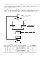
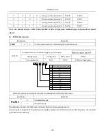
Page 155: ...ratio equation to calculate the ratio 6 Set parameters Set parameters using the calculated values Setting parameters procedure is as below Electric gearratio selection Electric gear ratio 1 1 Electri...

Page 156: ...er pulses 4 travel distance per load shaft rotation m n The actual meaning of electronic gear is Command pulse input Pulses numbers are X Y X A B A B Position command If the ratio is outside the setti...

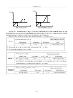
Page 157: ...ctronic gear ratio is higher than 10 times Po306 Position loop filter time constant Position Setting range Setting unit Mfr s value When enabled 1 10000 ms 1 Effective Immediate Setting position loop...

Page 158: ...ommand pulse inhibit INH P Must be allocated Inhibiting the servodrive from counting input pulses position pulse command is invalid 2 Setting parameters Parameters Remarks Po308 b 0 Terminal of inhibi...

Page 159: ...8 PL1 GND GND 40 HPULS HSIGN GND High speed pulse position command 3 4 HPULS 6 5 HPULS HSIGN HSIGN 24 GND Pulse output Po018 Internal position given Motor shaft Position command Frequency division out...

Page 160: ...hould be set by actual requirement At high speed Z pulse is narrow and it can be adjusted by Po017 Servo drive 37 30 OZ CM DC 5V 24V 2 Related parameters Po003 Molecule of encoder frequency division n...

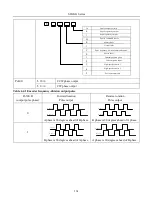
Page 161: ...r 1 Position command 4 5 Motor shaft High speed counter 2 Po300 b 0 CCW phase output b 1 CW phase output Table 6 4 1 Encoder frequency division output pulse Po300 D output pulse phase Forward rotation...

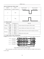
Page 162: ...coder Z phase home pulse output no frequency division PZO CN3 16 OZ CN3 37 Z phase open collector output CM CN3 30 4 Example of pulse frequency division signal Example when Po003 16 Po005 32768 the ea...

Page 163: ...effect Name Explanation Remark Po119 b 0 Reversal home searching Po119 b 1 Forward home searching Po119 b 0 Left right position limitation as home reference Po119 b 1 Input terminal ORGP as home refer...

Page 164: ...offset pulse Position Setting range Setting unit Mfr s value Effect 2147483647 2147483647 N A 0 Immediate effect Po128 Home searching signal duration time Speed Position Torque Setting range Setting u...

Page 165: ...e Chart 1 Po119 A b 1 Forward searching home reference at first speed after starting home search Po119 C b 1 1 Return back to search the nearest Z phase pulse as Mechanical originat the second speed w...

Page 166: ...signal ORGP Input signal SHOM Position Second speed First speed Fig 6 4 26 Reversal searching home at first speed 3 Po119 A b 1 Forward searching home reference at first speed after starting home sear...

Page 167: ...121 Po119 C 2 Po119 D 1 First speed Second speed Speed Position Z phase pulse Input signal ORGP Input signal SHOM Fig 6 4 28 Reversal home searching at first speed 5 Po119 A b 1 Forward searching home...

Page 168: ...st speed 7 Po119 A b 1 Forward home searching at first speed after starting home search Po119 C b 3 Search the rising edge of home reference ORGP as Mechanical origin Po125 A b 2 Input I O port to tri...

Page 169: ...ve Set mechanical origin as initial position the mechanical origin can be found in any position of forward reverse motion range set by servo motor AL 27 alarm will alerts if exceeding the setting moti...

Page 170: ...alue Speed Position Torque Setting Range Setting Unit Mfr s Value Effect 0 214748364 N A 0 Immediate effect 3 Mechanical Origin Search 1 User Parameters See chapter 6 4 8 for details 2 Sequence Chart...

Page 171: ...nal and motor cannot stop rotating instantly but run for a while setting in internal position mode During the operation period of fixed length interrupt drive shields any other internal external posit...

Page 172: ...upt start Trigger edge Register position trigger Rotary speed External position pulse mode Fixed length Internal position mode fixed length External position pulse mode Fig 6 4 36 Sequence chart when...

Page 173: ...al accuracy 1 Output signal Signal Abbr Default terminal Purport Position reach P CMP P CMP In position pulse mode P CMP In position pulse mode Positioning completed 2 Parameter Setting Po307 Position...

Page 174: ...plug M PG Control signal line plug PG Servo drive Passive measurement axis Main Traction Motion direction Fig 6 4 37 Full closed loop typical application sketch map CAUTION Connect power supply of ser...

Page 175: ...re of full closed loop shows as below Position feedback source setting Po376 Configure high speed counter PL100 Set alarm conditions Po379 Po380 Finish Set external encoder ratio Po377 Po378 Set feedb...

Page 176: ...78 is equal to the value that the encoder line number of servo motor divide by pulses of external encoder running if motor takes a turn 3 Set alarm output Po379 Mixed error remove turns Position Setti...

Page 177: ...A Open collector output Shileded wire connected to case High speed DI channel Position command High speed pulse position command Fig 6 4 39 Full closed loop mode typical wiring diagram CAUTION 1 One o...

Page 178: ...main circuit and control circuit correctly and also motor power line and encoder line JOG test run the servo drive by keypad to confirm the normal operation of motor Refer to the wiring instruction of...

Page 179: ...hro gain Po381 must not exceed position loop gain Po301 The setting procedure of gantry synchron is Start Interactive connection of two servo drives Position feedback source setting PL100 Alarm condit...

Page 180: ...te effect 3 Gain setting Po381 Gantry synchron gain Position Setting Range Setting Unit Mfr s value Effect 1 30000 N A 1 Immediate effect The value of Po381 cannot be higher than the value of position...

Page 181: ...hannel Shielded wire connected to case Open collector output Optocoupler output Max voltage 30 VDC Max current 50 mA Connected to PC PLC command Fig 6 4 43 Gantry synchron typical wiring diagram DI1 D...

Page 182: ...SD20 G Series 182 Fig 6 4 44SD20E Cam internal frameworkdiagram...

Page 183: ...cam point PL017 1 Use PC PLC to input points YES NO Conrfirm command source Po374 D Confirm cam condition PL000 B PL000 C Cam occlusive position setting PL003 Cam detachment point detachment conditio...

Page 184: ...ve command E Cam command position command Data Storage Address Data array start from PL200 area The data of driving shaft ahead driven shaft behind In communication mode for instance cam data is X Y b...

Page 185: ...of Master Axis is selected by PL000 B If PL000 B 0 command comes from high speed counter 1 If PL000 B 1 command comes from high speed counter 2 If PL000 B 2 command comers from internal position If PL...

Page 186: ...1 When the engaged condition is established the status is from STOP to Pre engaged The lead pulse is determined by PL003 Path 2 When the E cam function is disabled PL000A 0 it returns to STOP status P...

Page 187: ...P the E cam axis operates M cycle Then the setting of gear ratio PL007 M PL008 P CAM Function Set the relation between E cam axis slave axis and defined in the E cam table E cam axis operates one cycl...

Page 188: ...rates a cycle but the pulse command might not operate a cycle which can be set by users Description The slave axis is a virtual axis and the unit of slave position is the unit of user The pulse comman...

Page 189: ...ommand Source Position Setting Range Setting Unit Mfr s Value Effect Four parameters N A 0001 Immediate effect b A 0 1 Low speed pulse setting B 0 1 High speed counter setting C 0 1 Internal position...

Page 190: ...ate effect PL003 E cam Occlusion Contact Position Setting Range Setting Unit Mfr s Value Effect 2147483647 2147483647 N A 0 Immediate effect PL005 E cam Occlusion Release Point Position Setting Range...

Page 191: ...al address of E cam adjustment Position Setting Range Setting Unit Mfr s Value Effect 0 300 N A 0 Immediate effect PL023 Master axis variation Position Setting Range Setting Unit Mfr s Value Effect 21...

Page 192: ...peed of internal register and speed of external analog Po001 d 9 Speed of internal register and torque of external analog Po001 d 10 Speed and position of internal register Po001 d 11 Torque and posit...

Page 193: ...ing to deceleration time when speed selection signal is disabled Servo cannot reveive position pulse until switching to position mode after position arrive signal output is enabled In the running proc...

Page 194: ...to zero according to deceleration time when mode switching signal is enabled servo cannot receive position pulse until switching to position mode after position reach signal output is enabled In the...

Page 195: ...o slows down to zero according to deceleration time when mode witching signal is enabled servo cannot receive internal register position trigger signal until switching to internal register position mo...

Page 196: ...ero according to deceleration time when speed selection signal is disabled servo cannot receive internal register position trigger signal until switching to position mode after position reach signal o...

Page 197: ...ue mode servo slows down to zero according to deceleration time when mode switching signal is enabled servo cannot receive position pulse signal until switching to position pulse mode after position r...

Page 198: ...ocess of torque mode servo slows down to zero according to deceleration time when mode switching signal is enabled Servo cannot receive internal register position trigger signal until switching to int...

Page 199: ...ignal is disabled In the running process of position pulse mode when mode switching signal is enabled servo can receive internal position trigger only when position reach output signal is enabled In t...

Page 200: ...eration time In the running process of internal speed mode when speed selection signal is disabled servo switches to analog speed mode and run to analog setting speed according to acceleration deceler...

Page 201: ...time Torque Curve Internal Speed 3 Setting Torque Internal Speed Seleection 1 Internal Speed Seleection 2 Speed Curve Setting Torque Internal Speed 1 Internal Speed Selection 1 Internal Speed Selecti...

Page 202: ...de when mode selection signal is disabled and run to target speed according to acceleration deceleration time Speed Curve Mode Switch Analog Speed Setting Torque Torque Curve Mode Switch Setting Torqu...

Page 203: ...register torque mode when mode switching signal is disabled servo switches to analog torque mode and run to analog setting torque according to acceleration deceleration time Speed or Torque Curve Mod...

Page 204: ...rvo drive status display This parameter is used to set default display content in keypad Please refer to next table about the display item So 09 Servo drive status display speed position torque Settin...

Page 205: ...2 Analog speed command display 31 Gantry synchronous deviation 13 Analog torque command display 32 Reserved 14 D18 D15 status display 33 Hight speed counter 1 15 D14 D11status display 34 Hight speed c...

Page 206: ...temperature of motor is so high that make the motor excitation loss and damage and therefore servo drive provides motor overlaod protection function to prevent the damage from excessive temperature Se...

Page 207: ...tual current is very high servo drive and servo motor may be damaged because of long time lock rotor therefore servo drive provides the motor lock rotor protection to prevent the damage from excessive...

Page 208: ...valid logic Low level High Po438 Po445 Low Valid High level High Po438 Po445 Low Valid 0 1 N A 0 Effective Immediately 0 Invalid 1 Valid So 51 Temperature detection disconnection protection speed pos...

Page 209: ...eed position torque Setting Range Setting Unit Mfr s Value Effect 0 30000 N A 2 Immediate effect Po441 DI4 filter time speed position torque Setting Range Setting Unit Mfr s Value Effect 0 30000 N A 2...

Page 210: ...sponse accuracy rotation smoothness even cause motor oscillation SD20 servo drive can set friction torque compensation by software Sevo drive has three compensation points linear interpolation is used...

Page 211: ...rque Setting range Setting unit Mfr s value Effect 100 300 0 1 100 Effective Immediate Po293 Friction compensation coefficient 2 Speed Position Torque Setting range Setting unit Mfr s value Effect 0 1...

Page 212: ...will display AL 17 User can select encoder protection by So 15 So 15 Encoder disconnection protection Speed Position Torque Setting range Setting unit Mfr s value Effect 0 1 N A 1 Immediate effect 0 i...

Page 213: ...alarm current then this signal is output Signal Name Default terminal Remarks OL W Allocated by users Pre alarm signal of overload Related parameters So 35 Overload pre alarm current speed position to...

Page 214: ...grates the function of data capture which is using external or internal trigger signal to capture the position data of motion axis instantaneously and store to data array for the use of the follow up...

Page 215: ...PL101 C DI7 DI8 PULS SIGN CNT High speed counting area CNT value latched on the rising edge Reverse counting Forward counting Stop counting Start counting Reset CNT count value Counter CNT count value...

Page 216: ...mand Source Setting Finish High speed counter configuration Two Groups need YES NO Set PL121 Set PL120 Set two groups Set one group based on demands NO YES Cycle correction CAP function YES NO Configu...

Page 217: ...eed pulse type B 0 1 High speed pulse filtering 8MHz 4MHz Direction Pulse Dipulse 2 Orthogonal pulse 2 3 4 5 6 2MHz 1MHz 500KHz 200KHz 150KHz C 0 1 High speed pulse direction 2 3 D 0 1 DI7 DI8 filter...

Page 218: ...urce setting Software DI8 2 DI7 2 C 0 1 2 3 D 0 1 Close Start Software DI8 DI7 Command source setting Low speed pulse High speed pulse DI8 DI7 Duty cycle correction mode PL102 High speed counter 1 com...

Page 219: ...enabled Close CAP function Open CAP function Reverse Forward Disabled Enabled No Reset Reset PL111 High speed counter 2 command source speed position torque Setting Range Setting Unit Mfr s Value Effe...

Page 220: ...period When using the function of CAP period since CAP happens in random time of pulse servo drive will compare actual reveiced pulse with the pulse captured from edge then makes compensation to make...

Page 221: ...on of internal special area shows as followings Table8 1 Internal Special Area Area Bit addressing space Content Remark R0 B0 B15 Operating Mode Enabled when Po001 d 22 WR 0 Command Position 1 Command...

Page 222: ...B36 Command position mode activated receive RO Set 1 automatically when new command coming Reset after B35 resets B37 Command mode stop 1 Stop 0 Runnable B38 Speed mode stop acceleration deceleration...

Page 223: ...d Jog B91 Pulse prohibition B107 Reverse Jog B92 Emergency stop B108 Free B93 Reverse prohibition B109 Interruption fixed length release B94 Forward prohibition B110 Interruption fixed length start B9...

Page 224: ...ow speed timer enabled WR Addr Content Addr Content B368 Low speed timer 1 enabled B369 Low speed timer 2 enabled B370 Low speed timer 3 enabled B371 Low speed timer 4 enabled R24 B384 B399 Low speed...

Page 225: ...d B434 High speed timer 1 reset B435 High speed timer 1 direction B436 High speed timer 2 counting signal B437 High speed timer 2 enabled B438 High speed timer 2 reset B439 High speed timer 2 directio...

Page 226: ...signed number 6 8 3 1 Data Move Instruction The data moveinstruction is to transfer the source operands of register into the register assigned by destination operands The data transfer instruction of...

Page 227: ...er in R area MOVDDP L 3 P101 Po102 Po101 3 Immediate operand sends to no 101 register in P area MOVDRP R10 P101 Po102 Po101 R11 R10 No 10 register of R area transfers to no 101 register of Parea MOVDP...

Page 228: ...r of Y area the result sends to Z register address User can operate for R area P area and immediate operand See details as table 8 1 4 Table 8 1 4 32 bitAdd Instruction Syntax Results and related Anno...

Page 229: ...e value of P register the result sends to no 3 register in R area SUBWRP R1 P2 R3 R3 R1 P2 The value of R register subtracted to the value of P register the result sends to no 3 register in R area SUB...

Page 230: ...er address in Y area the result sends to Z register address User can operate for R area P area and immediate operand See details as table 8 1 7 Table 8 1 7 16 bit Multiplying Instruction Syntax Result...

Page 231: ...2 bit Multiplying Instruction Syntax Results and related Annotations Syntax Expression Running Results Annotations MULDRR R1 R2 R3 R6 R5 R4 R3 R2 R1 R3 R2 Multiplying the value of 2 registers in R are...

Page 232: ...ister address remainder stores to high bit register address User can operate for R area P area and immediate operand See details as table 8 1 9 Table 8 1 9 16 bit Division Instruction Syntax Results a...

Page 233: ...r stores to no 3 and no 4 registers remainder stores to no 6 and no 5 registers DIVDPR P1 R2 R3 R4 R3 R2 R1 R3 R2 R6 R5 R2 R1 R3 R2 Dividing the value of P register and R register the result saves to...

Page 234: ...tion code is instruction execution register address D is result scaling value X is multiplier Y is multiplicand Z is store result area User can operate for R area P area and immediate operand See deta...

Page 235: ...is result scaling value X is the register address which needs to covert Y is result storing register address User can operate for R area P area and immediate operand See details as table below Syntax...

Page 236: ...tion of series circuits with two or more contacts 3 OR Instruction There are 2 or instructions see details as below Instruction Format OR X Instruction Description OR is logic instruction means revers...

Page 237: ...1 R1 R1 1 The content of R1 register shift left one bit SHLWR P1 D1 Po001 Po001 1 The content of P1 register shift left one bit Table 8 1 16 16 bit Unsigned Right Shift Syntax Expression Running Resul...

Page 238: ...R1 register SALDP P1 D1 Po002 Po001 Po002 Po001 1 The content of P1 register shift left one bit of which high bit stores to P2 register low bit stores to P1 register Table 8 1 22 32 bit Unsighed Right...

Page 239: ...ory address Jump to specified address Execute the instruction and refresh control signal of low speed timer if current main loop has not finished executing instructions yet it will skip the rest instr...

Page 240: ...on code X is target register Output the result of program to X register address Syntax Expression Annotations OUT B100 Output the result of program to B100 register address 4 Main Control Instruction...

Page 241: ...at stores results take the content of X register address as absolute value and store the results into Y register Syntax Expression Running Result Annotations ABSDR R1 R3 R4 R3 ABS R2 R1 Take the conte...

Page 242: ...2 B0 Compare R1 register value with R2 register value send result into B0 B3 register CMPWDR D1 R2 B0 Compare immediate operand 1 with R2 register value send result into B0 B3 register CMPWPR P1 R2 B0...

Page 243: ...e then Z n 0 Z n 1 0 Z n 2 1 User can operate for R area P area and immediate operand See details as table below Syntax Expression Annotations CMPDRR R1 R2 B0 Compare R1 register value with R2 registe...

Page 244: ...o B0 B3 register 6 8 4 Built in PLC Parameters PL170 PLC Start Function PLC Setting Range Setting Unit Mfr s Value Effect 0 1 N A 0 Immediate Effect 0 Not start PLC function 1 Start PLC function PL172...

Page 245: ...imer 4 Configuration PLC Setting Range Setting Unit Mfr s Value Effect Two parameter N A 00 Immediate Effect d X 0 1 Y 0 1 10ms 100ms 2 PLC stores B451 Timer Mode Reach set value and maintain Reach se...

Page 246: ...er 4 current value PLC Setting Range Setting Unit Mfr s Value Effect 2147483647 2147483647 N A PL160 High speed counter 1 set PLC Setting Range Setting Unit Mfr s Value Effect Two parameter N A 00 Imm...

Page 247: ...ter 2 current value PLC Setting Range Setting Unit Mfr s Value Effect 2147483647 2147483647 N A 6 8 5 Built in PC PLC Use and Application Example To satisfy user requirement SD20 built in PLC adopts f...

Page 248: ...indow as following Fig 6 8 2 Communication setting window After finishing programing user can complie program If program is correct below window will pop up Fig 6 8 3 Program is correct If program is...

Page 249: ...d window will pop up user can press download key Note current software doesn t support ladder logic programing only suport language programming 6 8 5 1Application Example The application example illus...

Page 250: ...MOVWRP R29 P114 Send the result of R29 into Po114 it is convenient to check JUMP R100 Echoing with first sentence maintain the program in running status Case 4 16 bit Division Instruction MOVWDR D3 R...

Page 251: ...o DO1 MCR JUMP R100 Echoing with first sentence maintain the program in running status Case 8 Program Control Instruction Example MOVWDR D3 R30 Set program jump address LD B48 Judge DI1 status MC B464...

Page 252: ...2 MODBUSAddress and Contents Address Content Range Remarks 10000 Debug Mode WR 10001 Single step execution WR 10002 Running to breakpoint WR 10003 Breakpoint address WR 1175 Current address RO 10100 1...

Page 253: ...ocessing meets the needs Manual Adjustment Vibration Supression Finish YES NO Offline or online inertia identification Vibration Test Run YES NO Manual gain adjustment See chapter 7 4 3 for reference...

Page 254: ...ication Servo drive identifies current load inertia automatically according to the load condition the identified value writes to rotational inertia ratio Po013 1 If actual load inertia ratio is big an...

Page 255: ...rocess of offline inertia identification shows as below Start Servo enabled Po013 200 So 14 Press key Display stable Finish No Yes Servo enabled green light Current rotational inertia ratio Po008 1 Fo...

Page 256: ...ccel decel time speed position torque Setting Range Setting Unit Mfr s Value Effect 200 5000 ms 1000 Immediate effect 5 Rotational inertia ratio Po013 Rotational inertia ratio speedpositiontorque Sett...

Page 257: ...rpm s The machinery that rigid load is not easy to generate small vibration Slow changing of load inertia Mechanical clearance is not big in the motor process Start Servo enabled OFF Set Po008 3 PC PL...

Page 258: ...le illustrates as below The rigidity of servo drive is the ability that motor rotor overcomes load inertia which is self locking ability of motor rotor The stronger servo rigidity is the bigger corres...

Page 259: ...oportional gain Po101 first speed loop integral time Po102 first speed filter time constant Po105 first torque filter time constant Po214 first current loop bandwidth Po200 Table 7 3 1 Rigidity Level...

Page 260: ...directly connected with ball screw machine tool etc Setting method of rigidity level 1 Confirm that inertia identification has been executed and the inertia ratio is reasonable estimate proper rigidi...

Page 261: ...switching mode Po306 Position loop filter time constant Po131 Gain switching speed Po343 Position mode acel decel time Po132 Gain switching pulse Po229 Notch filter start Po133 Position loop gain swit...

Page 262: ...it does not change smoothly lower gain can reduce the vibration of system B Speed Loop Gain Po101 1st Speed loop proportional gain speed position torque Setting Range Setting Unit Mfr s Value Effect 0...

Page 263: ...ent loop bandwidth speed position torque Setting Range Setting Unit Mfr s Value Effect 10 3000 HZ Immediate effect Po201 2nd current loop bandwidth speed position torque Setting Range Setting Unit Mfr...

Page 264: ...Po130 0 No switch default to use gain 1 Po130 1 No switch default to use gain 2 Po130 2 Switch to gain 2 Immediate when speed is higher than the setting value of Po131 if speed is lower than Po131 aft...

Page 265: ...fect 1 32000 0 1ms 20 Immediate effect The time from one gain switching to another gain smoothly Po134 Speed loop gain switching time Position Speed Setting Range Setting Unit Mfr s Value Effect 0 200...

Page 266: ...frequency to reach vibration inhibition The principle of notch filter shows as below FL FH Notch bandwidth Notch depth Mechanical system Amplitude frequency characteristics Frequency Frequency Notch...

Page 267: ...ed in chapter 7 4 1 so is called low frequency resonance It can reduce the frequency effectively by the function of low frequency vibration inhibition Vibration in low frequency Servo Motor Coupling M...

Page 268: ...of parameter name When the parameter is reserved please do not set this kind of parameters 2 Instruction of parameter units The units of function selection parameters are N A they are no units 3 Instr...

Page 269: ...lse error numbers Command unit Valid in position pulse mode Lo 10 Given speed 0 1r min Valid in speed mode Lo 11 Given torque 1 of rated torque Valid in torque mode Lo 12 Analog speed command display...

Page 270: ...Closed Open Closed D DO4 0 1 Open Closed Lo 18 Current temperature display of servo drive Lo 19 Rotation inertia display 0 01 Lo 20 Current output torque display Lo 21 Current gain group display N A...

Page 271: ...tting unit Mfr s value Effect 0 9999 N A 0 Re power on Setting password is used to avoid modifying parameters by mistake The Mfr s value is 0 which means password is invalid and users can modify param...

Page 272: ...e duty ratio the faster discharge speed So 06 Input power phase loss protection Speed Position Torque Setting range Setting unit Mfr s value Effect 0 1 N A Immediate effect 0 phase loss protection is...

Page 273: ...of turns of encoder absolute position 8 Given command pulse numbers display low 5 digits 27 AI1 voltage 9 Given command pulse error numbers 28 AI2 voltage 10 Given speed 29 Combined deviation 11 Give...

Page 274: ...ate effect When brake motor is used So 16 is used to set speed threshold of electromagnetic brake Refer to 6 1 3 for details So 17 Forward run prohibited Speed Position Torque Setting range Setting un...

Page 275: ...peed Position Torque Setting range Setting unit Mfr s value Effect 1 500 1V 500 Effective Immediate So 22 Max rotation speed corresponding to 10V Speed Position Torque Setting range Setting unit Mfr s...

Page 276: ...arks 0 Absolute position In internal position absolute mode encoder feedback absolute position is adopted 1 Relative position Battery protection is shielded in internal position absolute mode encoder...

Page 277: ...tion Torque Setting range Setting unit Mfr s value Effect 10 1000 10ms 100 Effective Immediate So 41 Setting mechanical origin Speed Position Torque Setting range Setting unit Mfr s value Effect 0 1 N...

Page 278: ...o Mfr s value Speed Position Torque Setting range Setting unit Mfr s value Effect 0 1 N A 0 Repower on 0 invalid 1 valid When there is disorder with parameters and Mfr s value need to be restored set...

Page 279: ...ms 10 Effective Immediately So 61 Analog monitor channel 2 Speed Position Torque Setting range Setting unit Mfr s value Effect 0 3 N A 0 Effective Immediate Setting value Definition Remarks 0 Servo dr...

Page 280: ...mode of analog speed and position pulse Mix mode of analog torque and position pulse Mix mode of position pulse and internal register position Mix mode of analog speed and internal register torque Mi...

Page 281: ...d inertia Speed Position Torque Setting range Setting unit Mfr s value Effect 1 100 N A 10 Effective Immediate Po008 Rotary inertia mode Speed Position Torque Setting range Setting unit Mfr s value Ef...

Page 282: ...uch as machine tools etc 2 769 200 2500 1668 1000 0 3 1154 300 1666 1100 1000 0 4 1538 400 1250 830 1000 0 5 1923 500 1000 650 1000 0 6 2423 630 793 529 1000 0 7 2885 750 666 440 1000 0 8 3346 870 574...

Page 283: ...t 200 2147483647 N A Effective Immediate Please refer to 7 3 Po017 Z pulse frequency division output width Speed Position Torque Setting range Setting unit Mfr s value Effect 50 30000 N A Effective Im...

Page 284: ...000 0 1Hz 600 Effective Immediate Please refer to 7 3 3 Po102 First speed loop integral gain Speed Position Torque Setting range Setting unit Mfr s value Effect 0 10000 0 1ms 500 Effective Immediate P...

Page 285: ...peed mode Speed Setting range Setting unit Mfr s value Effect 1 30000 1ms 200 Effective Immediate Po110 Deceleration time only valid in speed mode Speed Setting range Setting unit Mfr s value Effect 1...

Page 286: ...limitation as home reference 0 0 B C 2 Nearest Z phase pulse as home reference Searching mechanical origin 0 1 Input terminal ORGP as home reference 1 3 2 Deceleration to stop after arriving at home r...

Page 287: ...range Setting unit Mfr s value Effect 0 3 N A 0 Effective Immediate 0 No home searching 1 Auto searching when power on 2 I O port trigger 3 Start Immediate Po126 Speed value in the zero clamp Speed Se...

Page 288: ...1 Po130 6 Switch to gain 2 Immediate if there is pulse input If there is no pulse input and the speed is lower than Po131 delay the setting time of Po135 0 1ms then switch to gain 1 Po131 Gain switchi...

Page 289: ...fect 0 32000 N A 1000 Effective Immediate Po143 Reverse running range pulse when overtravel protection Speed Position Torque Setting range Setting unit Mfr s value Effect 0 2147483647 N A 0 Effective...

Page 290: ...of rated torque 10 Effective Immediate Po207 Forward reverse run prohibited and emergency stop torque Speed Position Torque Setting range Setting unit Mfr s value Effect 1 300 1 of rated torque 100 Ef...

Page 291: ...ffective Immediate Po212 Torque increasing time Torque Setting range Setting unit Mfr s value Effect 0 30000 0 1ms 0 Effective Immediate Po213 Torque decreasing time Torque Setting range Setting unit...

Page 292: ...ting unit Mfr s value Effect 0 100 N A 0 Effective Immediate Please refer to 7 4 Po220 2nd Notch filter center frequency Speed Position Torque Setting range Setting unit Mfr s value Effect 50 30000 Hz...

Page 293: ...Setting unit Mfr s value Effect 0 100 N A 0 Effective Immediate Po229 Notch filter start Speed Position Torque Setting range Setting unit Mfr s value Effect 0 3 N A 0 Effective Immediate 0 Off 1 On 2...

Page 294: ...it Mfr s value Effect 0 1000 0 1 500 Effective Immediate Po237 Target torque range Torque Setting range Setting unit Mfr s value Effect 1 50 1 2 Effective Immediate Po238 Torque filter frequency Torqu...

Page 295: ...ative logic Po301 1st position loop gain Position Setting range Setting unit Mfr s value Effect 1 30000 N A Effective Immediate Po302 2nd position loop gain Position Setting range Setting unit Mfr s v...

Page 296: ...INH P must be allocated 0 Command pulse clear B 1 0 Position loop tracking error rate unit C 1 0 D 1 0 1 pulse 100 pulses Invalid Valid CLR must be Allocated Position loop tracking alarm rate unit 1 p...

Page 297: ...2000 ms 100 Effective Immediate Po316 Acceleration time of internal position 4 Internal register position Setting range Setting unit Mfr s value Effect 0 32000 ms 100 Effective Immediate Po317 Deceler...

Page 298: ...diate Po325 Deceleration time of internal position 8 Internal register position Setting range Setting unit Mfr s value Effect 0 32000 ms 100 Effective Immediate Po326 Filter time constant of position...

Page 299: ...Effect 1 65535 0 1r min 1000 Effective Immediate Po337 Given speed of postion 8 Internal register position Setting range Setting unit Mfr s value Effect 1 65535 0 1r min 1000 Effective Immediate Po338...

Page 300: ...sition mode Position Setting range Setting unit Mfr s value Effect 0 10000 ms 0 Effective Immediate Po344 2ed group electronic gear numerator Position Setting range Setting unit Mfr s value Effect 0 2...

Page 301: ...7 N A 0 Effective Immediate Po356 Given postion of postion 4 Internal register position Setting range Setting unit Mfr s value Effect 2147483647 2147483647 N A 0 Effective Immediate Po358 Given postio...

Page 302: ...t 0 32000 ms 0 Effective Immediate Po370 Interval time 5 Internal register position Setting range Setting unit Mfr s value Effect 0 32000 ms 0 Effective Immediate Po371 Interval time 6 Internal regist...

Page 303: ...from electronic cam On Off Pulse from high speed counter1 On Off Pulse from internal position On Off On Off Po376 Position feedback source Position Setting range Setting unit Mfr s value Effect 0 2 N...

Page 304: ...Gantry position feedback source Position Setting range Setting unit Mfr s value Effect 0 1 N A 0 Effective Immediate Po383 Gantry synchron alarm pulse Position Setting range Setting unit Mfr s value...

Page 305: ...ct 0 5000 mv 0 Effective Immediate Po403 AI2 torque command zero drift compensation Speed Position Torque Setting range Setting unit Mfr s value Effect 0 5000 mv 0 Effective Immediate Po404 Analog spe...

Page 306: ...r s value Effect Two parameter N A Repower on Po412 DI6 terminal function Speed Position Torque Setting range Setting unit Mfr s value Effect Two parameter N A Repower on Po413 DI7 terminal function S...

Page 307: ...ting unit Mfr s value Effect 100 5000 mv 2000 Effective Immediate Po427 Analog terminal control Speed Setting range Setting unit Mfr s value Effect 0 1 N A 0 Effective Immediate 0 Off 1 On Po428 Analo...

Page 308: ...o434 Torque corresponding to lower limit voltage in torque analog mode Speed PositionTorque Setting range Setting unit Mfr s value Effect 1000 1000 0 1 1000 Effective Immediate Please refer to 6 3 Po4...

Page 309: ...30000 N A 2 Effective Immediate Po442 DI5 filter time Speed Position Torque Setting range Setting unit Mfr s value Effect 0 30000 N A 2 Effective Immediate Po443 DI6 filter time Speed Position Torque...

Page 310: ...9600 3 19200 4 38400 5 57600 Po505 Permission of Read Write Speed Position Torque Setting range Setting unit Mfr s value Effect 0 1 N A 1 Effective Immediate 0 Permission of Read Write the communicati...

Page 311: ...Mfr s value Effect 1 30 pair Effective Immediate If servo motor is 8 polses Ho004 is 4 Ho005 Phase resistance Speed Position Torque Setting range Setting unit Mfr s value Effect 0 65535 10 3 Effective...

Page 312: ...Speed Position Torque Setting range Setting unit Mfr s value Effect 1 30000 N A 500 Effective Immediate 8 1 5 Alarm Record Parameters Ho2 Ho3 Ho200 Ho235 AL01 AL32 alarming times Speed Position Torque...

Page 313: ...value Effect Ho308 Motor speed at third last time alarm Speed Position Torque Setting range Setting unit Mfr s value Effect Ho310 Alarm code at last time Speed Position Torque Setting range Setting u...

Page 314: ...Setting unit Mfr s value Effect Ho319 Alarm code at tenth last time Speed Position Torque Setting range Setting unit Mfr s value Effect Ho320 Alarm time at last time Speed Position Torque Setting rang...

Page 315: ...27 Alarm time at eighth last time Speed Position Torque Setting range Setting unit Mfr s value Effect Ho328 Alarm time at ninth last time Speed Position Torque Setting range Setting unit Mfr s value E...

Page 316: ...nit Mfr s Value Effect 2147483647 2147483647 N A 0 Immediate effect PL005 E cam Occlusion Release Point Speed Position Torque Setting Range Setting Unit Mfr s Value Effect 2147483647 214748364 7 N A 0...

Page 317: ...te effect 0 Ready to start 1 Waiting for engaged trigger 2 Pre engaged Status 3 Running Status PL019 Master Axis Position Speed Position Torque Setting Range Setting Unit Mfr s Value Effect 0 21474836...

Page 318: ...enabled Close CAP function Open CAP function Reverse Forward Disabled Enabled No Reset Reset PL101 High speed counter 1 command source speed position torque Setting Range Setting Unit Mfr s Value Eff...

Page 319: ...Range Setting Unit Mfr s Value Effect 2147483647 2147483647 N A 0 Check PL110 High speed counter 2 control command speed position torque Setting Range Setting Unit Mfr s Value Effect Four parameter N...

Page 320: ...ffect PL114 High speed counter 2 periodic value speed position torque Setting Range Setting Unit Mfr s Value Effect 2147483647 2147483647 N A 0 Immediate effect PL116 High speed counter 2 count value...

Page 321: ...HPULS anti logic HSIGN positive logic HPULS positive logic HSIGN anti logic PL121 Internal command source speed position torque Setting Range Setting Unti Mfr s Value Effect 0 1 N A 0 Immediate effec...

Page 322: ...etting Unit Mfr s Value Effect Two parameter N A 00 Immediate Effect d X 0 1 Timer Mode Y 0 1 Count Source 10ms 100ms Reach set value and maintain Reach set value and continue to count 2 PLC stores B4...

Page 323: ...e Effect PL146 Low speed timer 4 set value PLC Setting Range Setting Unit Mfr s Value Effect 2147483647 2147483647 N A 0 Immediate Effect PL150 Low speed timer 1 current value PLC Setting Range Settin...

Page 324: ...fect Two parameter N A 00 Immediate Effect d X 0 1 Y 0 1 0 1ms PLC stores B436 Timer Mode Reach set value and maintain Reach set value and continue to count Count Source PL166 High speed counter 2 set...

Page 325: ...1 Reset PLC function PL199 Download of E cam and PLC data PLC Setting Range Setting Unit Mfr s Value Effect 0 1 N A 0 Immediate Effect When user refreshes cam table with PLC if communication mode is...

Page 326: ...n control 7 ZCLAMP Zero speed CLAMP 8 Gain switchover 9 10 CLR Pulse clear 11 INH P 12 ESP Emergency stop 13 R INH Reverse running prohibited 14 F INH Y Input contactor type selection 0 External switc...

Page 327: ...AMP When the absolute value of speed is lower than the value of zero speed CLAMP the motor speed is 0 and position is locked Level trigger 8 Gain switchover GAIN SEL Gain switchover Level trigger 9 In...

Page 328: ...lized by controlling terminal Level trigger 27 Terminal reverse jogging JOGD Realized by controlling terminal Level trigger 28 Motor overheat HOT Realized by controlling terminal Level trigger 29 Inte...

Page 329: ...Y is activated when the servo drive is ready to run All fault and alarm conditions if present have been cleared 1 Servo on SON O SON O is activated when the servo motor is ON 2 Rotation Detection TGON...

Page 330: ...2 Control power supply fault Check the voltage between L1C and L2C Note 380V servo drive doesn t need to connect to L1C and L2C 3 Servo drive fault Please contact with manufacturer Keypad panel displa...

Page 331: ...2 Rotation is not smooth at low speed Low speed rotation is not smooth Gain is not set properly Adjust gain according to chapter 7 Motor shaft vibrates side to side Rotation inertia ratio Po013 is too...

Page 332: ...n Check whether Lo 15 A is 1 if it is not check whether wiring is correct 2 Control mode is wrong Check whether Po001 X is correct Input position command Servo motor doesn t rotate or speed is not cor...

Page 333: ...solve the problem Servo motor is in unlocked state 1 Servo drive enabled signal is invalid Check whether green light is on if it is not take the following step Check whether Po004 0 if it is not set 0...

Page 334: ...07 Overspeed Speed is too high 8 AL 08 Reserved 9 AL 09 Large position control error Position loop trace error overflow 10 AL 10 Encoder fault Servo motor failure 11 AL 11 Emergency stop External eme...

Page 335: ...36 Parameter copy error Parameter copy error 37 AL 41 high impedance state not detected High impedance state output is not detected after 8 core encoder is powered on 9 3 Alarm Display Table and Trou...

Page 336: ...eed Servo motor rotary speed is higher than max speed Servo motor wiring encoder wiring or mechanical fault AL 08 Reserved AL 09 Large position control error U V W or encoder connection error or conne...

Page 337: ...ck if encoder cable is connected well If it is disconnected reconnect it and reset alarm 2 Check if battery level is 3 6V If level is lower than 3 2V keep control power at ON state 3 Shield AL 19 So 3...

Page 338: ...otor and encoder Wrong connection of encoder at mechanical terminal Check the connection of encoder at mechanical terminal Drive gain is low Increase gain adjust the gain of speed and position The fre...

Page 339: ...ectly Forward reverse rotation prohibited Make the function of forward reverse rotation prohibited invalid Torque limited Check the parameters of torque limited function Servodrive fault Maintain or r...

Page 340: ...es two ASCII characters 3 33H 1 31H Common characters ASCII characters are shown in the following table Characters 0 1 2 3 4 5 6 7 ASCII Code 30H 31H 32H 33H 34H 35H 36H 37H Characters 8 9 A B C D E F...

Page 341: ...Address Function Data CRC check End T1 T2 T3 T4 Servo drive Address Function Code N data Low order byte of CRC High order byte of CRC T1 T2 T3 T4 3 Protocol Converter It is easy to turn a RTU command...

Page 342: ...Servo motor feedback rotation low 16 bits 938 Servo motor absolution position rotation high16 bits 909 Servo motor feedback rotation high 16 bits 939 Servo motor absolution position rotation low 16 bi...

Page 343: ...highest bit 0 or 1 If the highest bit is 0 the data is actual servo motor feedback pulse numbers and the data is positive number If the highest bit is 1 to negate every bit and to add 1 to them which...

Page 344: ...ing Range Setting unit Mfr s value Remarks Po500 Communication address 1 254 1 Po501 Communication mode 0 1 0 0 RTU 1 ASCII Po502 Stop bit 0 1 0 0 1bit 1 2 bits Po503 Parity check selection 0 2 0 0 No...

Page 345: ...tion failure but higher current to certain elements as well 3 Grounding and Terminal Terminal resistance of 120 will be adopted for terminal of RS485 network to diminish the reflection of signals Term...

Page 346: ...de D7 D71 DB9 4BS02 3M 0 2 3M Battery box DB9 4BS02 5M 0 2 5M DB9 4BS02 10M 0 2 10M DB9 4GS02 3M 0 2 3M DB9 4GS02 5M 0 2 5M DB9 4GS02 10M 0 2 10M Encoder cable with L aviation plug applicable for 110...

Page 347: ...le with L aviation plug applicable for 110 130 and 180 flange servo motor Name Model Length Cable appearance 15 core encoder cable for D5 DB15 15GP01 3M 0 2 3M DB15 15GP01 5M 0 2 5M DB15 15GP01 10M 0...

Page 348: ...for servo motor with base No E F 11 2 Control cable Analog speed and torque mode control cable Name Model Length Appearance Control cable DB44 15AI 1M 0 2 1M DB44 15AI 2M 0 2 2M DB44 15AI 3M 0 2 3M Po...

Page 349: ...ger named as HK4B 4P0 M diameter Except servo motor with 180 flange other cables are named as HK4A 4P0 M diameter For M1 and M2 structure of 220V servo drive the name of cable should add B for M2 stru...

Page 350: ...length 11 5 Motor and matched cable 220V servo motor series Motor model Servo drive model Power cable model SMS series 3000r min SMSA 201 32 SD20 G201S2M1 SD20 G201T2M1 DB4 4PO M 0 75 B SMSA 401 32 S...

Page 351: ...22T2M2 HK4A 4PO M 1 0 B SMMB 152 37 SD20 G182S2M2 SD20 G182T2M2 HK4A 4PO M 1 5 B SMMB 232 37 SD20 G302T2M3 HK4A 4PO M 2 5 SMMB 272 3A HK4B 4PO M 2 5 SMMB 302 3A SD20 G452T2M3 HK4B 4PO M 4 0 SMMB 432 3...

Page 352: ...MMA 602 6A SD20 G752T3MM4 HK4B 4PO M 4 0 SMMA 752 6A SMMA 103 6A SD20 G153T3M4 HK4B 4PO M 6 0 SMM series 1500r min SMMB 122 67 SD20 G202T3M3 HK4A 4PO M 1 0 SMMB 152 67 SMMB 232 67 HK4A 4PO M 1 5 SMMB...

Page 353: ...M 6 0 SM17 0180 6EE FL SD20 G183T3M5 ZL4 4PO M 10 0 SM17 0210 6FE FL SD20 G223T3M5 ZL4 4PO M 10 0 SM17 0240 6EE FL SD20 G303T3M6 ZL4 4PO M 16 0 SM17 0270 6EE FL SD20 G303T3M6 ZL4 4PO M 16 0 SM17 0330...

Reviews: