SD20-G Series
70
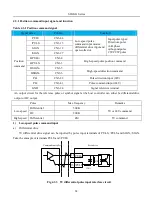
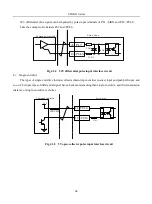
Passive contacts include relay contactor, limit switch, general key, button and so on. The common contact
circuit is as following figure:
24 VDC
3 .3 K
Servo drive
3 .3 K
GP
DI1
DI8
24 VDC
3 .3 K
Servo Drive
3 .3 K
GP
DI1
DI8
Fig 4-3-13 passive-contact interface circuit
(2) Active contactor
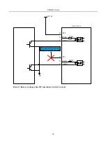
Active contactors include photoelectrical sensor, Hall sensor, transistor type PLC.
24VDC
3.3 K
Servo Drive
Controller
GP
DI1
3.3K
GP
24VDC
DI1
Controller
Servo Drive
NPN type PNP type
Fig 4-3-14 active contactor interface circuit
2)
Digital output circuit
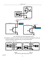
The output signal ALM and DO1~DO4 adopts photocoupler of Darlinton output which has strong ability for
drive and can drive small relay directly. It can drive heavier load by driving photocoupler. The max current
should not be higher than 50mA.
(1) Relay output
Summary of Contents for SD20-G Series
Page 35: ...SD20 G Series 35 M3 structure Fig 3 1 5 Servo drive structure 3...
Page 36: ...SD20 G Series 36 ML3 structure 118 5 5 7 5 93 297 8 223 118 93 0 5 12 5 7 5 4 M4...
Page 38: ...SD20 G Series 38 M4 structure Approx mass 10 365 kg Fig 3 1 7 Servo drive structure 5...
Page 39: ...SD20 G Series 39 M5 structure Approx msaa 11 1Kg Fig 3 1 8 Servo drive structure 6...
Page 40: ...SD20 G Series 40 M6 structure Approx mass 17 4Kg Fig 3 1 9 Servo drive structure 7...
Page 182: ...SD20 G Series 182 Fig 6 4 44SD20E Cam internal frameworkdiagram...


