SD20-G Series
53
X
Y
-
+
screw
Fig 4.1.6 main circuit terminals sketch diagram
Note: The figure above is only sketch, exact shape in kind prevail.
Table 4.1.1 SD20 series servo screw terminals dimension table
Structure
Main circuit terminals
X
(
mm
)
Y
(
mm
)
Screw
Locked Torque
(
Nm
)
M3
9.9
13.0
M4
1.24
(
Max
)
MM4
10.2
12.7
M4
1.46
M4
11.7
16
M6
2.5
M5
13
16
M5
2.0
M6
20.3
23.5
M8
2.8
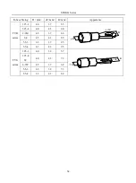
EURA recommends below tube cable lug for wiring:
Table 4.1.2 Tube cable lug dimension and appearance
Summary of Contents for SD20-G Series
Page 35: ...SD20 G Series 35 M3 structure Fig 3 1 5 Servo drive structure 3...
Page 36: ...SD20 G Series 36 ML3 structure 118 5 5 7 5 93 297 8 223 118 93 0 5 12 5 7 5 4 M4...
Page 38: ...SD20 G Series 38 M4 structure Approx mass 10 365 kg Fig 3 1 7 Servo drive structure 5...
Page 39: ...SD20 G Series 39 M5 structure Approx msaa 11 1Kg Fig 3 1 8 Servo drive structure 6...
Page 40: ...SD20 G Series 40 M6 structure Approx mass 17 4Kg Fig 3 1 9 Servo drive structure 7...
Page 182: ...SD20 G Series 182 Fig 6 4 44SD20E Cam internal frameworkdiagram...


