SD20-G Series
343
Ex4
:
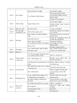
The address of servo motor feedback pulse numbers
From the above table, the address of servo motor feedback pulse includes high 16 bits (Communication address is
906, the hex form is 0x038A) and low 16 bits(Communication address is 907, the hex form is 0x038B). Read the
data from the address and process them.
4 Reading and writing rules of parameters
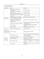
Except two-parameter and four-parameter, the other parameters can be read directly, the data is 16-bit integer (it
is complement form).
Concerning for two-parameter and four-parameter, the written and read value is hexadecimal format (The
marking bits of d and b do not occupy communication bit). Under line “_” means that the bit is not displayed.
Ex5
:
Two-parameter mode is d_1_10, so the hex format is 0x10A, so the read result is 266.
Ex6
:
Four-parameter mode is b1234, so 0x1234 is written, and b1234 is displayed after the order succeeds.
The special instructions for 32-bit data are as the following.
Ex7
:
Read servo motor feedback pulse numbers. Separately read high 16-bit and low 16-bit parameters value,
shift high 16-bit data 16 bits to the left, and execute OR with low 16-bit, and confirm positive and negative
according to the highest bit 0 or 1. If the highest bit is 0, the data is actual servo motor feedback pulse numbers and
the data is positive number. If the highest bit is 1, to negate every bit and to add 1 to them, which equals to servo
motor feedback pulse numbers and it is a negative number. If high 16 bit is 65534 and low bit is 31073, the binary
form of which is 1111111111111110 and 111100101100001, after shifting high 16-bit data to the left, the data
becomes 11111111111111100111100101100001. The highest data is 1, so the data is negative. Negate the data, the
data becomes 11000011010011110, and add 1 to the data, the data becomes 11000011010011111, the decimal
form is 99999. Because it is a negative number, so it is -99999.
Bit mode meaning in monitor group:
The parameter meaning in address 923:
MSB
←
LSB
16
15
14
13
12
11
10
9
8
7
6
5
4
3
2
1
—
—
—
—
—
—
—
—
DI8
DI7
DI6
DI5
DI4
DI3
DI2
DI1
The parameter meaning in address 925:
MSB
←
LSB
16
15
14
13
12
11
10
9
8
7
6
5
4
3
2
1
—
—
—
—
—
—
—
—
—
—
—
DO5
DO4
DO3
DO2
DO1
The parameter meaning in address 926
,
940
MSB
←
LSB
16
15
14
13
12
11
10
9
8
7
6
5
4
3
2
1
AL-16 AL-15 AL-14 AL-13 AL-11 AL-10 AL-10 AL-09 AL-08 AL-07 AL-06 AL-05 AL-04 AL-03 AL-02 AL-01
Note: “—” means “reserved”, which is used to add new function.
• 5 Example:
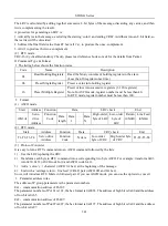
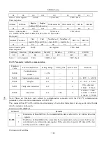
(1) In RTU mode, change acc time (Po109) to 5ms in No. 01 servo drive.
Host query:
Address
Function
Register
Address
Hi
Register
Address
Lo
Write status Hi Write status Lo
CRC Lo
CRC Hi
Summary of Contents for SD20-G Series
Page 35: ...SD20 G Series 35 M3 structure Fig 3 1 5 Servo drive structure 3...
Page 36: ...SD20 G Series 36 ML3 structure 118 5 5 7 5 93 297 8 223 118 93 0 5 12 5 7 5 4 M4...
Page 38: ...SD20 G Series 38 M4 structure Approx mass 10 365 kg Fig 3 1 7 Servo drive structure 5...
Page 39: ...SD20 G Series 39 M5 structure Approx msaa 11 1Kg Fig 3 1 8 Servo drive structure 6...
Page 40: ...SD20 G Series 40 M6 structure Approx mass 17 4Kg Fig 3 1 9 Servo drive structure 7...
Page 182: ...SD20 G Series 182 Fig 6 4 44SD20E Cam internal frameworkdiagram...


