SD20-G Series
61
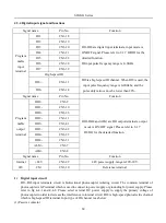
4.3 I/O signal wiring
PULSE
SIGN
Position
command
Connect shielded wire to shell
Photocoupler output
Max voltage: 30 VDC
Max current : 50 mA
Servo drive
DI1
DI2
DI3
DI4
DI5
DI6
38
DI7
39
GP
2
18
19
20
21
22
11
26
41
42
9
10
ALM+ 7
ALM- 8
PA0+ 36
PA0-
PULS
35
15
PB0+
44
34
PB0-
33
PZ0+ 16
/PULS
SIGN
PZ0-
12
17
27 /SIGN
D04+ 32
OZ
31
DI8-
14
12V
|
24V
D02+
D03+
D02-
D03-
D01+
43 PL2
28 PL1
D01-
Encoder pulse
Frequency-division
output
GND
AGND 40
HPULS
HSIGN
GND
High -speed
Pulse position
command
3
4 HPULS+
6
5
HPULS-
HSIGN+
HSIGN-
24 GND
Position pulse mode
Analog speed
-10 to +10V
External torque
limit
23
AS1
AS 2 25
24
GND
GND
24
Lowpass filter
A/D convert
Analog speed mode, torque mode
D04-
37
CM
+24V 29
CM
30
+ 24V
Command receiver
DC: 5V- 24V
30
Lowpass filter
Max current 100mA
DI8+
13
High-speed DI
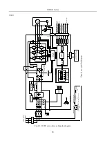
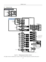
Fig 4.3.1 Wiring diagram in 3 kinds of modes
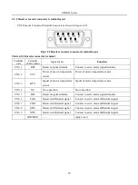
I/O signal connector terminal layout (connect to CN3) is as following fig when viewed from the solder
Summary of Contents for SD20-G Series
Page 35: ...SD20 G Series 35 M3 structure Fig 3 1 5 Servo drive structure 3...
Page 36: ...SD20 G Series 36 ML3 structure 118 5 5 7 5 93 297 8 223 118 93 0 5 12 5 7 5 4 M4...
Page 38: ...SD20 G Series 38 M4 structure Approx mass 10 365 kg Fig 3 1 7 Servo drive structure 5...
Page 39: ...SD20 G Series 39 M5 structure Approx msaa 11 1Kg Fig 3 1 8 Servo drive structure 6...
Page 40: ...SD20 G Series 40 M6 structure Approx mass 17 4Kg Fig 3 1 9 Servo drive structure 7...
Page 182: ...SD20 G Series 182 Fig 6 4 44SD20E Cam internal frameworkdiagram...


