SD20-G Series
84
The system (machinery or appliance) installed with the servo drive must also have the CE mark. The system
integrator is responsible for compliance of the system with the EMC directives and standard EN 61800-3: 2004
Category C2.
If applied in the first environment, the servo drive may generate radio interference. Besides the CE compliance
described in this chapter, users must take measures to avoid such interference, if necessary.
4.5.3 Selection and Installation of Peripheral EMC Devices
An EMC filter installed between the servo drive and the power supply can not only restrict the interference of
electromagnetic noise in the surrounding environment on the servo drive, but also prevent the interference from
the servo drive on the surrounding equipment. SD20 works with external filter and input filter according to
different power rating. The installation precautions are as follows.
1)
Strictly comply with the ratings when using the EMC filter. The EMC filter is category I electric apparatus,
and therefore, the metal housing ground of the filter should be in good contact with the metal ground of the
installation cabinet on a large area, and requires good conductive continuity. Otherwise, it will result in
electric shock or poor EMC effect.
2)
The ground of the EMC filter and the PE conductor of the servo drive must be tied to the same common
ground. Otherwise, the EMC effect will be affected seriously.
3)
The EMC filter should be installed as closely as possible to the power input side of the servo drive.
4.5.4 Shielded Cable
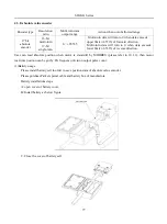
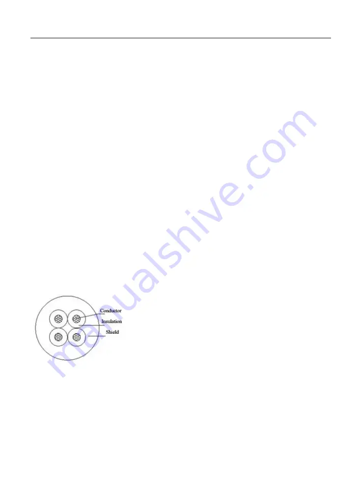
The shielded cable must be used to satisfy the EMC requirements of CE marking. The Shielded cable are shown in
the following figure
To suppress emission and conduction of the radio frequency interference effectively, the shield of the shielded
cable is cooper braid. The braided density of the cooper braid should be greater than 90% to enhance the shielding
efficiency and conductivity, as shown in the following figure.
Summary of Contents for SD20-G Series
Page 35: ...SD20 G Series 35 M3 structure Fig 3 1 5 Servo drive structure 3...
Page 36: ...SD20 G Series 36 ML3 structure 118 5 5 7 5 93 297 8 223 118 93 0 5 12 5 7 5 4 M4...
Page 38: ...SD20 G Series 38 M4 structure Approx mass 10 365 kg Fig 3 1 7 Servo drive structure 5...
Page 39: ...SD20 G Series 39 M5 structure Approx msaa 11 1Kg Fig 3 1 8 Servo drive structure 6...
Page 40: ...SD20 G Series 40 M6 structure Approx mass 17 4Kg Fig 3 1 9 Servo drive structure 7...
Page 182: ...SD20 G Series 182 Fig 6 4 44SD20E Cam internal frameworkdiagram...


