SD20-G Series
99
Table 6.1.2 terminal definition (0:open 1:close)
K1
K2
Running command
0
0
Stop
0
1
Stop
1
0
Forward runnning
1
1
Reverse running
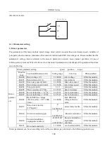
(3)Three-line mode 1
X is enable terminal, motor direction is determined by FWD and REV,
Enable terminal must be disconnected when user stops drive.
Rising edge is valid.
Servo drive
K1
K2
FWD
REV
K3
X
GP
K1: Forward running K2: Reverse running K3: Enable terminal
(4)Three-line mode 2
X is enable terminal, running command is given by FWD, motor direction is determined by REV.
Enable terminal must be disconnected when user stops drive.
K2 is closed, motor direction is reverse, K2 is open, motor direction is forward.
Servo drive
K1
K2
FWD
REV
K3
X
GP
(5)Direction and pulse mode
FWD terminal controls motor rotation by inspecting pulse edge. When pulse is triggered, motor starts runing
forwardly, when pulse is triggered again, motor is stopped. REV terminal has the same function, except motor
Summary of Contents for SD20-G Series
Page 35: ...SD20 G Series 35 M3 structure Fig 3 1 5 Servo drive structure 3...
Page 36: ...SD20 G Series 36 ML3 structure 118 5 5 7 5 93 297 8 223 118 93 0 5 12 5 7 5 4 M4...
Page 38: ...SD20 G Series 38 M4 structure Approx mass 10 365 kg Fig 3 1 7 Servo drive structure 5...
Page 39: ...SD20 G Series 39 M5 structure Approx msaa 11 1Kg Fig 3 1 8 Servo drive structure 6...
Page 40: ...SD20 G Series 40 M6 structure Approx mass 17 4Kg Fig 3 1 9 Servo drive structure 7...
Page 182: ...SD20 G Series 182 Fig 6 4 44SD20E Cam internal frameworkdiagram...


