


SD20-G Series
112
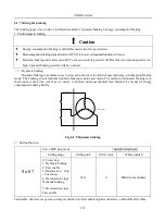
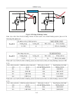
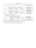
Dc bus P
N
B1
B2
B3
N+
Built-in
braking resistor
Dc bus
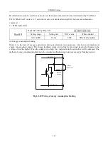
Remove the wire between B2 and B3, and
connect resistor between B1 and B2.
P
N
B1
B2
B3
N+
Dc bus
Dc bus
Built-in
braking resistor
Fig 6-1-11 Wiring of braking resistor
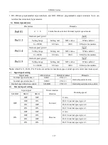
Some servo drives have built-in braking resistor, if users need to use external braking resistor, please set the
following both parameters:
So-04
Resistance value of braking resisto
Speed Position Torque
Setting range
Setting unit
Mfr’s value
When enabled
8~1000
Ω
—
Effective Immediate
So-05
Discharge duty ratio
Speed Position Torque
Setting range
Setting unit
Mfr’s value
When enabled
0~100
%
50
Effective Immediate
Please refer to next table for built-in braking resistor and min resistor value of external braking resistor for 220V
servo.
Servo drive structure
code
Built-in resistor value and
power
Min resistor value of
external braking resistor
Specification of external
braking resistor
M1
None
40Ω
60Ω/200 W
M2
50W/50Ω
25Ω
40Ω/ 400 W
M3
100W/20Ω
15Ω
15Ω/ 1000 W
M4
260W/15Ω
10Ω
15Ω/2000 W
Please refer to next table for built-in braking resistor and min resistor value of external braking resistor for 380V
servo.
Servo drive structure
code
Built-in resistor value and
power
Min resistor value of
external braking resistor
Specification of external
braking resistor
M2
50W/50Ω
50Ω
50Ω/1000W
M3
100W/60Ω
50Ω
50Ω/1000W
Summary of Contents for SD20-G Series
Page 35: ...SD20 G Series 35 M3 structure Fig 3 1 5 Servo drive structure 3...
Page 36: ...SD20 G Series 36 ML3 structure 118 5 5 7 5 93 297 8 223 118 93 0 5 12 5 7 5 4 M4...
Page 38: ...SD20 G Series 38 M4 structure Approx mass 10 365 kg Fig 3 1 7 Servo drive structure 5...
Page 39: ...SD20 G Series 39 M5 structure Approx msaa 11 1Kg Fig 3 1 8 Servo drive structure 6...
Page 40: ...SD20 G Series 40 M6 structure Approx mass 17 4Kg Fig 3 1 9 Servo drive structure 7...
Page 182: ...SD20 G Series 182 Fig 6 4 44SD20E Cam internal frameworkdiagram...