SD20-G Series
252
6.8.6 Built-in PLC Communication Operation
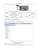
6.8.6.1 MODBUS Address
MODBUS address of PL area start from 1000, see details for built-in PLC address as table below:
Table 1: MODBUS address of built-in PLC area
Address
Content
Range
Remarks
1170
PLC start
0
~
1
1172
PLC start address
0
~
2000
1174
PLC reset
0
~
1
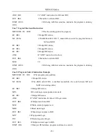
6.8.6.2 DEBUG function of built-in PLC
Table 2: MODBUSAddress and Contents
Address
Content
Range
Remarks
10000
Debug Mode
WR
10001
Single step execution
WR
10002
Running to breakpoint
WR
10003
Breakpoint address
WR
1175
Current address
RO
10100
~
10355
Data of R0
~
R255
WR
Table 3: DEBUG Mode Function
Action
Debug
mode
Single step
Running to
breakpoint
Breakpoint
address
Running to breakpoint address N, then
enter single step mode.
1
0
1
N
In single step mode, single-step executes
one instruction, and single-step execute
automatic reset
1
1
0
N
Pause in current instruction
1
0
0
N
Run the program normally
0
0
0
N
Summary of Contents for SD20-G Series
Page 35: ...SD20 G Series 35 M3 structure Fig 3 1 5 Servo drive structure 3...
Page 36: ...SD20 G Series 36 ML3 structure 118 5 5 7 5 93 297 8 223 118 93 0 5 12 5 7 5 4 M4...
Page 38: ...SD20 G Series 38 M4 structure Approx mass 10 365 kg Fig 3 1 7 Servo drive structure 5...
Page 39: ...SD20 G Series 39 M5 structure Approx msaa 11 1Kg Fig 3 1 8 Servo drive structure 6...
Page 40: ...SD20 G Series 40 M6 structure Approx mass 17 4Kg Fig 3 1 9 Servo drive structure 7...
Page 182: ...SD20 G Series 182 Fig 6 4 44SD20E Cam internal frameworkdiagram...


