SD20-G Series
49
IV Wiring
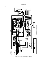
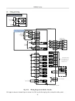
This chapter provides servo system block diagram.
220V
K
M
1
L
1
L
3
L
2
B
1
B
2
B
3
M
D
C
-D
C
co
n
v
er
si
o
n
S
er
v
o
al
ar
m
R
L
Y
N
o
rm
al
ly
o
p
en
co
n
ta
ct
M
a
n
u
al
p
o
w
er
o
n
S
el
f-
lo
ck
co
n
ta
ct
o
r
N
o
rm
al
ly
o
p
en
co
n
ta
ct
K
M
1
+
-
+
¨C
U
V
W
P
E
+
5
V
1
5
V
+
1
5
V
+
2
4
V
+
3
.3
V
N
+
D
ri
v
e
ci
rc
u
it
R
el
ay
C
h
a
rg
e
en
er
g
y
d
is
si
p
at
io
n
b
ra
k
e
ci
rc
u
it
In
te
rf
ac
e
ci
rc
u
it
D
S
P
M
C
U
CN 3 input and output signal
terminal
CN2 encoder input signal terminal
+
+
F
P
G
A
A
/D
P
G
U
V
W
P
E
P
o
si
ti
o
n
p
u
ls
e
co
m
m
an
d
in
p
u
t
D
if
fe
re
n
ti
al
b
u
s
O
p
ti
ca
l
Is
o
la
ti
o
n
C
N
1
S
er
ia
l
C
o
m
m
u
n
ic
at
io
n
P
C
/P
L
C
o
r
o
th
e
r
p
ro
g
ra
m
m
a
b
le
c
o
n
tr
o
ll
e
rs
O
u
t-
p
h
as
e
d
et
ec
ti
n
g
D
y
n
a
m
ic
b
ra
k
in
g
ci
rc
u
it
F
a
n
ci
rc
u
it
+
2
4
V
N
-
L
1
C
L
2
C
P
E
T
h
re
e-
p
h
as
e
p
o
w
er
su
p
p
ly
E
M
I
F
il
te
r
F
ig
4
-1
-1
S
er
v
o
sy
st
e
m
b
lo
c
k
d
ia
g
r
a
m
D
A
K
ey
p
ad
p
an
el
+
M
an
u
al
p
o
w
er
o
ff
S
el
f-
lo
c
k
c
o
n
ta
ct
o
r
K
M
1
O
p
ti
ca
l
Is
o
la
ti
o
n
D
if
fe
re
n
ti
al
b
u
s
A
n
al
o
g
sp
ee
d
co
m
m
an
d
in
p
u
t
A
n
al
o
g
to
rq
u
e
co
m
m
an
d
in
p
u
t
D
ig
it
al
in
p
u
t
D
ig
it
al
o
u
tp
ut
A
n
al
o
g
m
o
n
it
o
r
o
u
tp
u
t
E
n
co
d
er
si
g
n
al
fr
eq
u
en
cy
-d
iv
is
io
n
o
u
tp
u
t
Fig 4.1.1 220V servo drive schematic diagram
Summary of Contents for SD20-G Series
Page 35: ...SD20 G Series 35 M3 structure Fig 3 1 5 Servo drive structure 3...
Page 36: ...SD20 G Series 36 ML3 structure 118 5 5 7 5 93 297 8 223 118 93 0 5 12 5 7 5 4 M4...
Page 38: ...SD20 G Series 38 M4 structure Approx mass 10 365 kg Fig 3 1 7 Servo drive structure 5...
Page 39: ...SD20 G Series 39 M5 structure Approx msaa 11 1Kg Fig 3 1 8 Servo drive structure 6...
Page 40: ...SD20 G Series 40 M6 structure Approx mass 17 4Kg Fig 3 1 9 Servo drive structure 7...
Page 182: ...SD20 G Series 182 Fig 6 4 44SD20E Cam internal frameworkdiagram...


