SD20-G Series
140
①
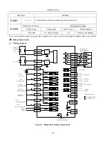
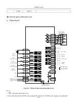
Pulse command input terminal
Servo drive has 2 groups of pulse command input terminals.
PULSE
SIGN
PULS
15
44
/ PULS
SIGN 12
27
/ SIGN
43
PL2
28
PL1
HPULS
HSIGN
GND
High-speed
pulse position
command
3
4
HPULS+
6
5
HPULS-
HSIGN+
HSIGN-
24
GND
Servo drive
24V Command
interface
24V
Low-speed
pulse position
command
command
interface
● Low-speed pulse input terminals (PL2, PULS+, PL1, SIGN+, SIGN-) can accept differential input signal
(input pulse max frequency is 500Khz) and open collector input signal(input pulse max frequency is 200Khz).
●High-speed pulse input terminals (HPULS+, HPULS-,HSIGN+,HSIGN-) can accept 5V differential input
signal(input pulse max frequency is 4Mhz).
②
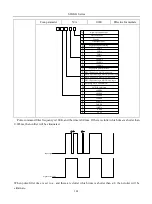
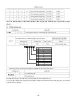
Pulse input pin filter
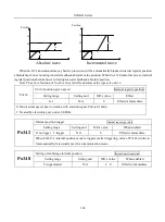
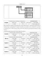
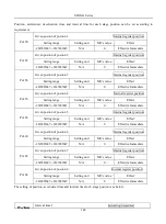
For low-speed pulse or high-speed pulse input terminal, filter time need to be set to filter input pulse command,
in order to prevent interference signal.
Parameter
Remarks
Po300
b □□0□
Pulse input filter frequency is 4MHz
b □□1□
Pulse input filter frequency is 2MHz
b □□2□
Pulse input filter frequency is 1MHz
b □□3□
Pulse input filter frequency is 500KHz
b □□4□
Pulse input filter frequency is 200KHz
b □□5□
Pulse input filter frequency is 150KHz
b □□6□
Pulse input filter frequency is 80kHz
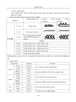
PL120
High-speed pulse control
speed position torque
Setting range
Setting unit
Mfr’s value
When enabled
Summary of Contents for SD20-G Series
Page 35: ...SD20 G Series 35 M3 structure Fig 3 1 5 Servo drive structure 3...
Page 36: ...SD20 G Series 36 ML3 structure 118 5 5 7 5 93 297 8 223 118 93 0 5 12 5 7 5 4 M4...
Page 38: ...SD20 G Series 38 M4 structure Approx mass 10 365 kg Fig 3 1 7 Servo drive structure 5...
Page 39: ...SD20 G Series 39 M5 structure Approx msaa 11 1Kg Fig 3 1 8 Servo drive structure 6...
Page 40: ...SD20 G Series 40 M6 structure Approx mass 17 4Kg Fig 3 1 9 Servo drive structure 7...
Page 182: ...SD20 G Series 182 Fig 6 4 44SD20E Cam internal frameworkdiagram...


