SD20-G Series
11
II Model selection
2.1 Servo drive introduction
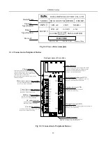
2.1.1 Servo Drive Nameplate
M2
Product series
-
G 102 T3 M2
M4
M5
420
x
210
x 234
218
x
100
x
203
380
x
185
x 215
M6
270 x
234
498x
SD20
MM4
336
150
203
x
x
Product usage
Fieldbus type
E
Power
201
102
Input Voltage
380V
T3
Frame size
(
WxHxD)
F0
Communication
Modbus
EtherCAT
F5
D20
Encoder type
Resolver
D20
D50
D51
14-core 2500 ppr incremental encoder
8-core 2500 ppr incremental encoder
B3
Braking
B1/ default
Dynamic braking
S2
T2
1-phase 220V
3-phase 220V
M3
195
x
48
x
175
M3(5.5kW)
195
x
75
x
175
218
x
100
x
203
M1
Bake type
B3
B3
B1
B1
B1
B1
B1
B1
B1
B3
3-phase
(No built-in braking resistor)
D52
D70
D71
4-core 23-bit incremental encoder
4-core 17-bit absolute encoder
4-core 23-bit absolute encoder
101
(No built-in braking resistor)
(No built-in braking resistor)
(No built-in braking resistor)
(No built-in braking resistor)
G
General
...
...
100W
200W
1KW
CANopen
F4
F0/default
Energy consumption braking
(built-in braking resistor)
B2
B3
B6
Energy consumption braking
+Dynamic braking
Energy consumption braking
(external braking resistor)
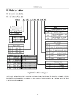
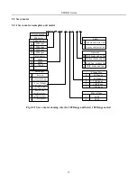
Fig 2.1.1 Servo Drive naming rule
Note: Servo drives of M1-MM4 structure have no buit-in filter, use can select external filter to satisfy EMC R3
standard
. Full details are given in chapter 2.4. Servo drives of M4-M6 structure have optional built-in R3 filter,
it depends on user’s selection.
Summary of Contents for SD20-G Series
Page 35: ...SD20 G Series 35 M3 structure Fig 3 1 5 Servo drive structure 3...
Page 36: ...SD20 G Series 36 ML3 structure 118 5 5 7 5 93 297 8 223 118 93 0 5 12 5 7 5 4 M4...
Page 38: ...SD20 G Series 38 M4 structure Approx mass 10 365 kg Fig 3 1 7 Servo drive structure 5...
Page 39: ...SD20 G Series 39 M5 structure Approx msaa 11 1Kg Fig 3 1 8 Servo drive structure 6...
Page 40: ...SD20 G Series 40 M6 structure Approx mass 17 4Kg Fig 3 1 9 Servo drive structure 7...
Page 182: ...SD20 G Series 182 Fig 6 4 44SD20E Cam internal frameworkdiagram...


