SD20-G Series
261
7.3.3 Manual Gain Adjustment
User can make fine adjustment manually when the automatic gain adjustment cannot reach the expected
effect.
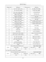
Table 7.3.2Manual Gain Adjustment Parameter Table
Parameter
Name
Parameter
Name
Po101
1
st
Speed loop proportional gain
Po135
Gain 2 switch to gain 1 delay time
Po102
1
st
Speed loop integral time
Po200
1
st
current loop bandwidth
Po103
2
nd
Speed loop proportional gain
Po201
2
nd
current loop bandwidth
Po104
2
nd
Speed loop integral time
Po214
1
st
torque filter time constant
Po105
1
st
Speed loop time constant
Po215
2
nd
torque filter time constant
Po106
2
nd
Speed loop filter time constant
Po301
1
st
position loop gain
Po107
Torque feedforward gain
Po302
2
nd
position loop gain
Po108
Torque feedforward gain filter
Po303
Position loop feedforward gain
Po130
Gain switching mode
Po306
Position loop filter time constant
Po131
Gain switching speed
Po343
Position mode acel/decel time
Po132
Gain switching pulse
Po229
Notch filter start
Po133
Position loop gain switching time
Po217
1
st
Notch filter center frequency
Po134
Speed loop gain switching time
Po218
1
st
Notch filter width
Po219
1
st
Notch filter depth
Po220
2
nd
Notch filter center frequency
Po221
2
nd
Notch filter width
Po222
2
nd
Notch filter depth
Po223
3
rd
Notch filter center frequency
Po224
3
rd
Notch filter width
Po225
3
rd
Notch filter depth
Po226
4
th
Notch filter center frequency
Po227
4
th
Notch filter width
Po228
4
th
Notch filter depth
Po240
Vibration suppression central
frequency
Po241
Reserved
Po242
Vibration suppression intensity
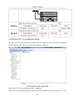
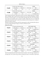
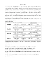
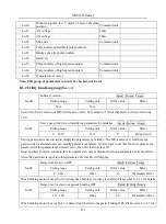
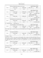
(1) User Parameter Illustration
A) Position Loop Gain
Po301
1
st
position loop gain
Position
Setting Range
Setting Unit
Mfr’s Value
Effect
1~30000
N/A
—
Immediate effect
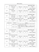
Po302
2
nd
position loop gain
Position
Setting Range
Setting Unit
Mfr’s Value
Effect
1~30000
N/A
—
Immediate effect
Summary of Contents for SD20-G Series
Page 35: ...SD20 G Series 35 M3 structure Fig 3 1 5 Servo drive structure 3...
Page 36: ...SD20 G Series 36 ML3 structure 118 5 5 7 5 93 297 8 223 118 93 0 5 12 5 7 5 4 M4...
Page 38: ...SD20 G Series 38 M4 structure Approx mass 10 365 kg Fig 3 1 7 Servo drive structure 5...
Page 39: ...SD20 G Series 39 M5 structure Approx msaa 11 1Kg Fig 3 1 8 Servo drive structure 6...
Page 40: ...SD20 G Series 40 M6 structure Approx mass 17 4Kg Fig 3 1 9 Servo drive structure 7...
Page 182: ...SD20 G Series 182 Fig 6 4 44SD20E Cam internal frameworkdiagram...

