2-39
D
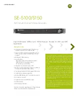
Power Supply Sequence
200-V class:
Three-phase, 200 to
230 VAC (50/60 Hz)
400-V class:
Three-phase, 380 to
460 VAC (50/60 Hz)
Power
supply
Inverter
(See note)
L1 (R)
L2 (S)
L3 (T)
Note Use a transformer with 200- and 400-V outputs for the power supply of the 400-V Inverter.
2-2-5 Wiring Control Circuit Terminals
A control signal line must be 50 m maximum and separated from power lines. The fre-
quency reference must be input to the Inverter through twisted-pair wires.
H
Wire Size and Round Solderless Terminals
Use thick wires to prevent voltage drops if the wires are long.
D
Wires for All Inverter Models
Terminal
Terminal
screw
Wire thickness (mm
2
)
Type
1 to 11, 13 to 33
M3.5
Stranded wire: 0.5 to 1.25
Single wire: 0.5 to 1.25
Shielded, twisted-pair wire
Shielded,
polyethylene-covered vinyl
12 (G)
M3.5
0.5 to 2
polyethylene-covered, vinyl
sheath cable
D
Round Solderless Terminals for Ground Terminal
Wire thickness
(mm
2
)
Terminal
screw
Size
Screw torque
(N
S
m)
0.5
M3.5
1.25 to 3.5
0.8
0.75
1.25 to 3.5
1.25
1.25 to 3.5
2
2 to 3.5
H
Considerations When Wiring Control Circuit Terminals
•
Wire control signal lines separately from the main circuit lines and other power lines.
•
Wire control circuit terminals 9, 10, 18, 19, and 20 (contact outputs) separately from terminals 1 to 8,
21, 22, 23, 25, 26, 27, 33, and 11 to 17.
•
Connect shielded wire to terminal 12(G).
•
Insulate the shielded areas with tape to prevent contact with other signal lines and equipment.
Installation
Chapter 2
Summary of Contents for SYSDRIVE 3G3FV
Page 1: ...USER S MANUAL High function General purpose Inverter SYSDRIVE 3G3FV Cat No I516 E1 4 ...
Page 16: ...Chapter 1 Introduction 1 1 Function 1 2 Nomenclature 1 3 New Functions 1 ...
Page 33: ...Chapter 2 Installation 2 1 Mounting 2 2 Wiring 2 ...
Page 112: ...Chapter 4 Trial Operation 4 1 Procedure 4 2 Operation Example 4 ...
Page 289: ...Chapter 7 Parameter Lists 7 1 Initialize Mode Parameters 7 2 Program Mode Parameter List 7 ...
Page 366: ...Chapter 9 Specifications 9 1 Inverter Specifications 9 2 Option Specifications 9 ...
Page 395: ...Chapter 10 Appendix 10 1 Notes on Using the Inverter for a Motor 10 ...