


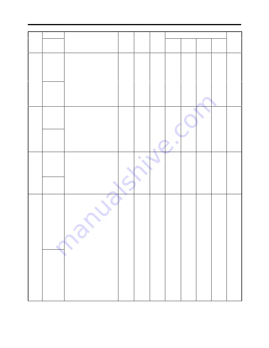
7-45
Para
meter
No.
Page
Control mode
Chan-
ges
during
opera-
tion
Default
setting
Setting
range
Description
Name
Para
meter
No.
Page
Flux
vector
Open
loop
vector
V/f
with
PG
V/f
control
Chan-
ges
during
opera-
tion
Default
setting
Setting
range
Description
Display
name
L2-03
Minimum
baseblock
time (BB)
Sets the Inverter’s minimum
baseblock time in units of one
second, when the Inverter is
restarted after power loss
ridethrough.
Note: Sets the time for the mo-
tor’s residual voltage to
0.1 to
5.0
0.5
(See
note 1.)
NO
B
B
B
B
6-100
PwrL
Baseblock t
tor s residual voltage to
dissipate.
When an overcurrent oc-
curs when starting a
speed search or DC injec-
tion braking, increase the
set values.
L2-04
Voltage
restart time
Sets the time required to return
to normal voltage at the
completion of a speed search,
in units of one second.
Note: Set the time required for a
200 V class Inverter to re
0.0 to
5.0
0.3
NO
A
A
A
A
6-100
PwrL V/F
Ramp t
200-V class Inverter to re-
cover from 0 V to
200 VAC.
(For the 400-V class In-
verter, the time from 0 V
to 400 VAC.)
L2-05
Under
voltage
detection
level (UV)
Sets the main circuit under
voltage (UV) detection level
(main circuit DC voltage) in V
units.
Note: Usually setting is not nec-
essary. Insert a AC reac-
150 to
210
(See
note 2.)
190
(See
note 2.)
NO
A
A
A
A
6-100
PUV Det
Level
essary. Insert a AC reac-
tor and use this function
to lower the main circuit
under voltage detection
level.
L2-06
KEB
deceleration
rate
By decelerating simultaneously
with a momentary power
interruption, this function
produces regenerative energy
and utilizes this energy to
counter the power interruption.
Select the deceleration rate to
be applied after the KEB
command (set value: 65 or 66)
set for multi-function inputs is
input.
Set as a percentage the
deceleration frequency rate for
when the time set in L2 02 has
0.0 to
100.0
0.1
NO
A
A
A
A
---
KEB
Frequency
when the time set in L2-02 has
elapsed after KEB command
input.
If 80% is set, deceleration will
be performed taking the time set
in L2-02, up to 80% of the
output frequency when KEB is
input.
If L2-06 is set to 0.0, C1-09 will
automatically decelerate to the
base so that the undervoltage
(UV) of the main circuit will not
be detected.
Note 1. The default setting depends upon the type of Inverter. The values for a 200-V class 0.4-kW
Inverter arre given above.
Note 2. These are values for a 200-V class Inverter. Values for the 400-V class Inverter are double.
Parameter Lists
Chapter 7
Summary of Contents for SYSDRIVE 3G3FV
Page 1: ...USER S MANUAL High function General purpose Inverter SYSDRIVE 3G3FV Cat No I516 E1 4 ...
Page 16: ...Chapter 1 Introduction 1 1 Function 1 2 Nomenclature 1 3 New Functions 1 ...
Page 33: ...Chapter 2 Installation 2 1 Mounting 2 2 Wiring 2 ...
Page 112: ...Chapter 4 Trial Operation 4 1 Procedure 4 2 Operation Example 4 ...
Page 289: ...Chapter 7 Parameter Lists 7 1 Initialize Mode Parameters 7 2 Program Mode Parameter List 7 ...
Page 366: ...Chapter 9 Specifications 9 1 Inverter Specifications 9 2 Option Specifications 9 ...
Page 395: ...Chapter 10 Appendix 10 1 Notes on Using the Inverter for a Motor 10 ...