


6-43
•
For the DC injection braking current (b2-02), set the value for the current that is output at the time of DC
injection braking. DC injection braking current is set as a percentage of Inverter rated output current,
with the Inverter rated output current taken as 100%. If the DC injection braking time (parameters
b2-03 and b2-04) is longer than one second, set the DC injection braking current to 50% or less.
•
For the DC injection braking time at start (b2-03), set the DC injection braking operating time for when
the motor is started.
•
For the DC injection braking time at stop (b2-04), set the DC injection braking operating time for when
the motor is stopped.
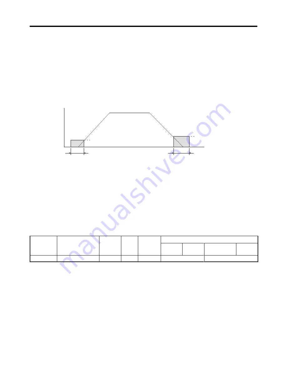
DC Injection (Initial Excitation) Timing Chart
E1-09
(Min. output frequency)
b2-03
(DC injection braking time at start)
b2-04
(DC injection braking
time at stop)
Time
The larger of b2-01
or E1-09
Output frequency
H
Setting Magnetic Field Compensation (b2-08)
When using the “DC injection braking at startup” (initial excitation) function to bring up the motor’s mag-
netic flux before running machinery that requires high starting torque, it may take some time for the
magnetic flux to rise sufficiently. This depends upon the motor’s electrical time constant, and is espe-
cially true with high-capacity motors.
This function can be used to apply a stronger magnetic flux current when the “DC injection braking at
startup” (initial excitation) function starts, so that the magnetic field in the motor rises faster and more
reliably.
Parameter
Display name
Setting
Units
Default
Valid access levels
number
p y
g
range
setting
V/f
Control
V/f with
PG
Open Loop
Vector
Flux
Vector
b2-08
Field Comp@start
0 to 500
1%
0
Not applicable.
Advanced
This parameter cannot be changed during operation.
Note When b2-08 is 100%, it indicates the motor’s no-load current value (motor magnetic flux current).
Advanced Operation
Chapter 6
Summary of Contents for SYSDRIVE 3G3FV
Page 1: ...USER S MANUAL High function General purpose Inverter SYSDRIVE 3G3FV Cat No I516 E1 4 ...
Page 16: ...Chapter 1 Introduction 1 1 Function 1 2 Nomenclature 1 3 New Functions 1 ...
Page 33: ...Chapter 2 Installation 2 1 Mounting 2 2 Wiring 2 ...
Page 112: ...Chapter 4 Trial Operation 4 1 Procedure 4 2 Operation Example 4 ...
Page 289: ...Chapter 7 Parameter Lists 7 1 Initialize Mode Parameters 7 2 Program Mode Parameter List 7 ...
Page 366: ...Chapter 9 Specifications 9 1 Inverter Specifications 9 2 Option Specifications 9 ...
Page 395: ...Chapter 10 Appendix 10 1 Notes on Using the Inverter for a Motor 10 ...