


6-99
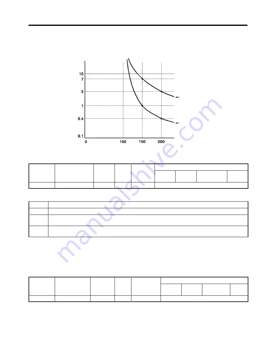
Electronic Thermal Time Characteristics
In this example, L1-02 is set to 1 minute, the motor is operating at 60 Hz, and general-purpose motor
characteristics are used.
Operating time (minutes)
Cold start
Hot start
Motor current (%)
(E2-01 is 100%.)
H
Momentary Power Loss Settings (L2)
Parameter
Display name
Setting
Units
Default
Valid access levels
number
p y
g
range
setting
V/f
Control
V/f with
PG
Open Loop
Vector
Flux
Vector
L2-01
PwrL Selection
0 to 2
---
0
Basic or Advanced
Note This parameter cannot be changed during operation.
Setting
Function
0
Disabled. (An under-voltage fault is detected when there is a momentary power loss.)
1
Enabled. (Restarts if power is restored within the L2-02 time. An under-voltage fault is detected for
a longer power loss.)
2
Enabled during CPU operation. (Restarts if power is restored while the CPU is operating. An
under-voltage fault is not detected.)
•
This parameter specifies the processing that is performed when a momentary power loss occurs.
•
When power-loss ridethrough is enabled (setting 1 or 2), operation will be restarted after a speed
search if the power is restored within the allowed time interval.
•
When power-loss ridethrough is disabled (setting 0), an under-voltage fault will be detected if power is
interrupted for more than 15 ms.
Parameter
Display name
Setting
Units
Default
*2
Valid access levels
number
p y
g
range
setting
*2
V/f
Control
V/f with
PG
Open Loop
Vector
Flux
Vector
L2-02
PwrL Ridethru t
0.0 to 2.0
s
0.5
Basic or Advanced
Note 1. This parameter cannot be changed during operation.
Note 2. The default setting depends on the Inverter’s capacity. The default setting shown in the table
is for a 200-V class, 0.4-kW Inverter.
•
This setting is valid only when parameter L2-01 is set to 1.
Advanced Operation
Chapter 6
Summary of Contents for SYSDRIVE 3G3FV
Page 1: ...USER S MANUAL High function General purpose Inverter SYSDRIVE 3G3FV Cat No I516 E1 4 ...
Page 16: ...Chapter 1 Introduction 1 1 Function 1 2 Nomenclature 1 3 New Functions 1 ...
Page 33: ...Chapter 2 Installation 2 1 Mounting 2 2 Wiring 2 ...
Page 112: ...Chapter 4 Trial Operation 4 1 Procedure 4 2 Operation Example 4 ...
Page 289: ...Chapter 7 Parameter Lists 7 1 Initialize Mode Parameters 7 2 Program Mode Parameter List 7 ...
Page 366: ...Chapter 9 Specifications 9 1 Inverter Specifications 9 2 Option Specifications 9 ...
Page 395: ...Chapter 10 Appendix 10 1 Notes on Using the Inverter for a Motor 10 ...