


6-104
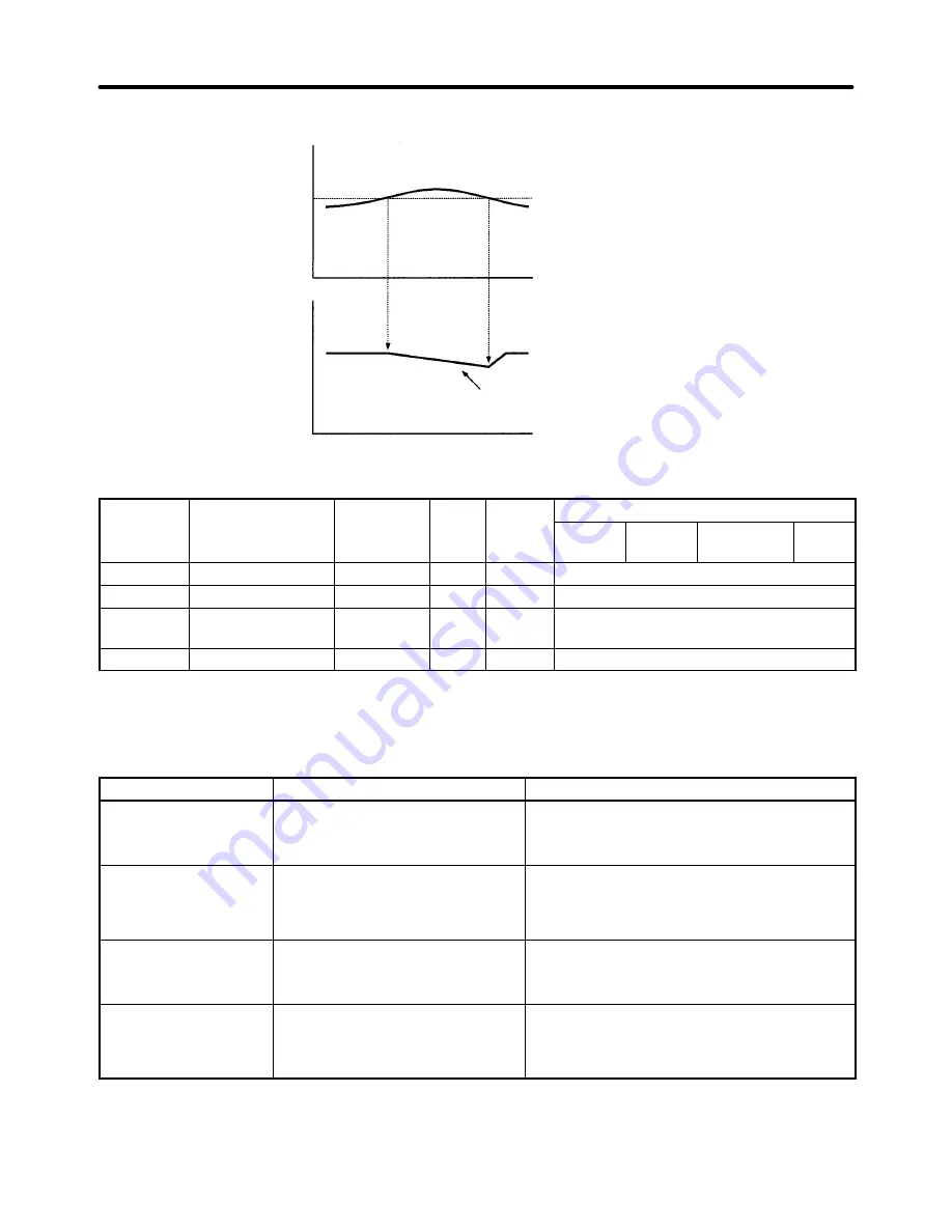
Run Stall Prevention Example: L3-05 = 1 or 2
Output current
Output frequency
L3-06 (Run stall prevention level)
The output frequency is controlled
to prevent stalling.
Time
Time
H
Frequency Detection Settings (L4)
Parameter
Display name
Setting
Units
Default
Valid access levels
number
p y
g
range
setting
V/f
Control
V/f with
PG
Open Loop
Vector
Flux
Vector
L4-01
Spd Agree Level
0.0 to 400.0 Hz
0.0
Basic or Advanced
L4-02
Spd Agree Width
0.0 to 20.0
Hz
2.0
Basic or Advanced
L4-03
Spd Agree Lvl+–
–400.0 to
+400.0
Hz
0.0
Advanced
L4-04
Spd Agree Wdth+– 0.0 to 20.0
Hz
2.0
Advanced
Note These parameters cannot be changed during operation.
•
Set these parameters when outputting one of the frequency agree or frequency detection signals from
a multi-function output (settings 2, 3, 4, 5, 13, 14, 15, or 16). The following table shows the relationship
between these parameters and the output signals.
Parameter
Related output settings
Parameter function
Speed Agree Level
(Absolute value)
Fref/Set Agree 1 (setting 3)
Frequency Detection 1 (setting 4)
Frequency Detection 2 (setting 5)
Set the speed that you want to detect in Hz.
The set speed is an absolute value, so the
speed is detected in forward or reverse.
Speed Agree Width
(Absolute value)
Fref/Fout Agree 1 (setting 2)
Fref/Set Agree 1 (setting 3)
Frequency Detection 1 (setting 4)
Frequency Detection 2 (setting 5)
Set the speed detection range in Hz.
Speed Agree Level +/–
(Signed value)
Fref/Set Agree 2 (setting 14)
Frequency Detection 3 (setting 15)
Frequency Detection 4 (setting 16)
Set the speed that you want to detect in Hz.
Set positive values for forward, negative
values for reverse.
Speed Agree Width +/–
(Signed value)
Fref/Fout Agree 2 (setting 13)
Fref/Set Agree 2 (setting 14)
Frequency Detection 3 (setting 15)
Frequency Detection 4 (setting 16)
Set the speed detection range in Hz.
•
Set the corresponding setting in the multi-function output (H2-01, H2-02, or H2-03) to output the de-
sired Fref/Fout Agree signal, Fref/Set Agree signal, or Frequency Detection signal. There is a timing
chart showing the operation of these signals on the following page.
Advanced Operation
Chapter 6
Summary of Contents for SYSDRIVE 3G3FV
Page 1: ...USER S MANUAL High function General purpose Inverter SYSDRIVE 3G3FV Cat No I516 E1 4 ...
Page 16: ...Chapter 1 Introduction 1 1 Function 1 2 Nomenclature 1 3 New Functions 1 ...
Page 33: ...Chapter 2 Installation 2 1 Mounting 2 2 Wiring 2 ...
Page 112: ...Chapter 4 Trial Operation 4 1 Procedure 4 2 Operation Example 4 ...
Page 289: ...Chapter 7 Parameter Lists 7 1 Initialize Mode Parameters 7 2 Program Mode Parameter List 7 ...
Page 366: ...Chapter 9 Specifications 9 1 Inverter Specifications 9 2 Option Specifications 9 ...
Page 395: ...Chapter 10 Appendix 10 1 Notes on Using the Inverter for a Motor 10 ...