


2-47
D
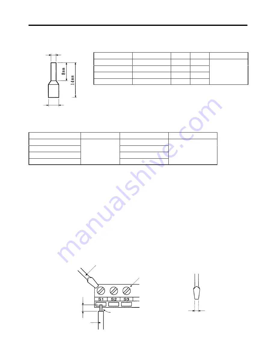
Solderless Terminals for Control Circuit Terminals
The use of solderless terminals for the control circuit terminals is recommended because solderless
terminals are easy to connect securely.
Wire thickness
Model
d1
d2
Manufacturer
0.5 mm
2
A1 0.5-8WH
1.00
2.60
Phoenix Contact
0.75 mm
2
A1 0.75-8GY
1.20
2.80
1 mm
2
A1 1-8RD
1.40
3.00
1.5 mm
2
A1 1.5-8BK
1.70
3.50
Note Do not solder wires with the control circuit terminals if wires are used instead of solderless termi-
nals. Wires may not contact well with the control circuit terminals or the wires may be discon-
nected from the control circuit terminals due to vibration if the wires are soldered.
D
Round Solderless Terminal Sizes and Screw Torque
Wire thickness (mm
2
)
Terminal screw
Size
Screw torque (N
S
m)
0.5
M3.5
1.25 to 3.5
0.8
0.75
1.25 to 3.5
1.25
1.25 to 3.5
2
2 to 3.5
H
Wiring Control Circuit Terminals
D
Wiring Method
1. Loosen the terminal screws with a thin-slotted screwdriver.
2. Insert the wires from underneath the terminal block.
3. Tighten the terminal screws firmly.
Note 1. Always separate the control signal line from the main circuit cables and other power cables.
Note 2. Do not solder the wires to the control circuit terminals. The wires may not contact well with the
control circuit terminals if the wires are soldered.
Note 3. The end of each wire connected to the control circuit terminals must be stripped for approxi-
mately 7 mm.
Note 4. Use a shielded wire for the ground terminal.
Note 5. Insulate the shield with tape so that the shield will not touch any signal line or device.
Strip the end for 7 mm if
no solderless terminal is
used.
Wires
Thin-slotted screwdriver
Control circuit
terminal block
Solderless terminal or
wire without soldering
Blade of screwdriver
3.5 mm max.
Blade thickness: 0.6 mm max.
Installation
Chapter 2
d1 dia.
d2 dia.
Summary of Contents for SYSDRIVE 3G3FV
Page 1: ...USER S MANUAL High function General purpose Inverter SYSDRIVE 3G3FV Cat No I516 E1 4 ...
Page 16: ...Chapter 1 Introduction 1 1 Function 1 2 Nomenclature 1 3 New Functions 1 ...
Page 33: ...Chapter 2 Installation 2 1 Mounting 2 2 Wiring 2 ...
Page 112: ...Chapter 4 Trial Operation 4 1 Procedure 4 2 Operation Example 4 ...
Page 289: ...Chapter 7 Parameter Lists 7 1 Initialize Mode Parameters 7 2 Program Mode Parameter List 7 ...
Page 366: ...Chapter 9 Specifications 9 1 Inverter Specifications 9 2 Option Specifications 9 ...
Page 395: ...Chapter 10 Appendix 10 1 Notes on Using the Inverter for a Motor 10 ...