


6-78
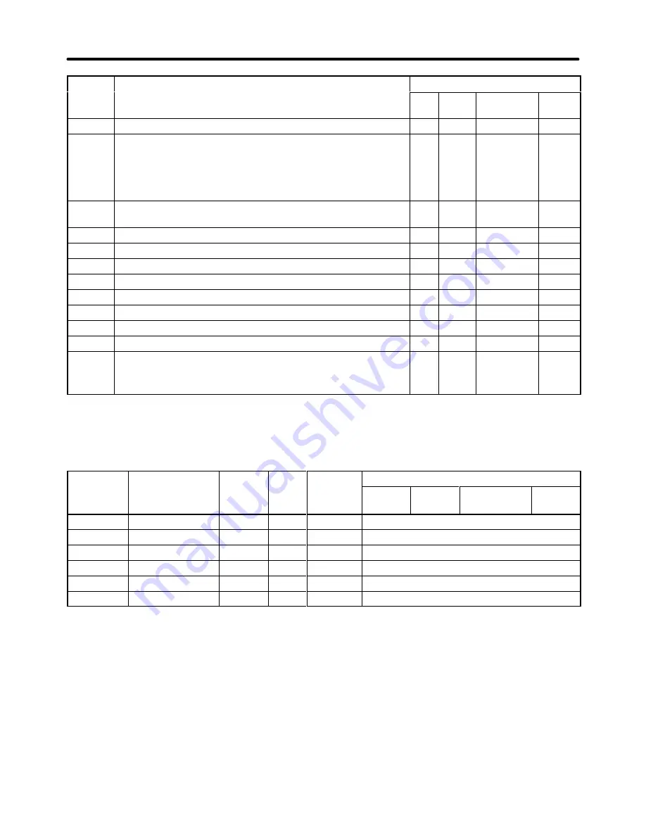
Setting
Control mode
Function
Setting
Flux
Vector
Open-loop
Vector
V/f
w/PG
V/f
Function
1F
Terminal 13/14 Switch (Selects terminal 14 when ON.)
OK
OK
OK
OK
20 to
2F
External Fault
(Any combination of the following can be set as needed.)
Input: Normally open or normally closed
Detection mode: Always or During operation only
Stopping method: Decel, Coast, Emergency, or Continue
OK
OK
OK
OK
30
PID Integral Reset (ON: Resets the integral value with I
control disabled.)
OK
OK
OK
OK
31
PID Integral Hold (ON: Retains the integral value.)
OK
OK
OK
OK
60
DC Injection Activate (Performs DC braking when ON.)
OK
OK
OK
OK
61
External search 1 (Speed search from max. frequency)
OK
---
OK
---
62
External search 2 (Speed search from frequency reference)
OK
---
OK
---
63
Energy-saving operation (according to b8-01 and b8-02)
OK
OK
---
---
64 to 66 Not used. (Do not input this setting.)
---
---
---
---
71
Speed Torque Control Change (Torque Control when ON.)
---
---
---
OK
72
Zero-servo Command (Zero Servo operation when ON.)
---
---
---
OK
77
ASR Gain Switch
ON: Use proportional gain in C5-03.
OFF: Calculate gain from C5-01, C5-03, and C5-07.
---
---
---
OK
D
Parameter Settings
The following table shows the setting information for multi-function inputs 1 through 6. These parame-
ters cannot be changed during operation.
Parameter
Display name
Setting
Units
Default
*1
Valid access levels
number
p y
g
range
setting
*1
V/f
Control
V/f with
PG
Open Loop
Vector
Flux
Vector
H1-01
Terminal 3 Sel
0 to 77
---
24
Basic or Advanced
H1-02
Terminal 4 Sel
0 to 77
---
14
Basic or Advanced
H1-03
Terminal 5 Sel
0 to 77
---
3 (0)
Basic or Advanced
H1-04
Terminal 6 Sel
0 to 77
---
4 (3)
Basic or Advanced
H1-05
Terminal 7 Sel
0 to 77
---
6 (4)
Basic or Advanced
H1-06
Terminal 8 Sel
0 to 77
---
8 (6)
Basic or Advanced
Note 1. The default settings in parentheses are the default settings when the Unit is initialized for
3-wire control.
Note 2. The following table shows the settings and page references for some common functions.
Advanced Operation
Chapter 6
Summary of Contents for SYSDRIVE 3G3FV
Page 1: ...USER S MANUAL High function General purpose Inverter SYSDRIVE 3G3FV Cat No I516 E1 4 ...
Page 16: ...Chapter 1 Introduction 1 1 Function 1 2 Nomenclature 1 3 New Functions 1 ...
Page 33: ...Chapter 2 Installation 2 1 Mounting 2 2 Wiring 2 ...
Page 112: ...Chapter 4 Trial Operation 4 1 Procedure 4 2 Operation Example 4 ...
Page 289: ...Chapter 7 Parameter Lists 7 1 Initialize Mode Parameters 7 2 Program Mode Parameter List 7 ...
Page 366: ...Chapter 9 Specifications 9 1 Inverter Specifications 9 2 Option Specifications 9 ...
Page 395: ...Chapter 10 Appendix 10 1 Notes on Using the Inverter for a Motor 10 ...