


5-4
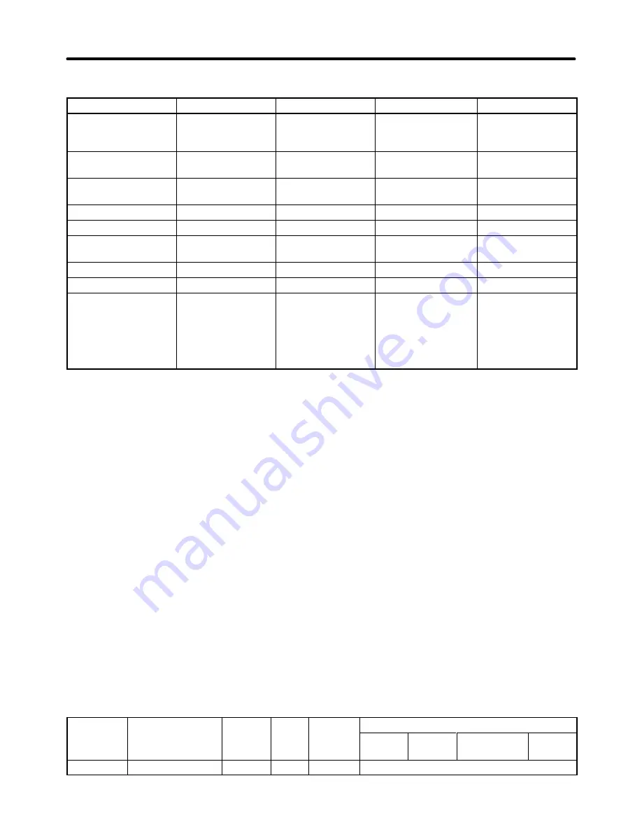
Control Mode Characteristics
Characteristic
V/f Control
V/f w/PG Fdbk
Open Loop Vector
Flux Vector
Basic control method
Voltage/frequency
control (open loop)
Voltage/frequency
control with speed
compensation
Current vector con-
trol without PG
Current vector con-
trol with PG
Speed detector
Not required
Required
(pulse generator)
Not required
Required
(pulse generator)
Optional Speed
Detectors
Not required
3G3FV-PPGA2 or
3G3FV-PPGD2
Not required
3G3FV-PPGB2 or
3G3FV-PPGX2
Speed control range
1:40
1:40
1:100
1:1,000
Starting torque
150%/3 Hz
150%/3 Hz
150%/1 Hz
150%/0 Hz
Speed control preci-
sion
±
2 to 3%
±
0.03%
±
0.2%
±
0.02%
Torque limit
Not possible
Not possible
Possible
Possible
Torque control
Not possible
Not possible
Not possible
Possible
Example applications
•
Multiple motors
•
Simple speed
feedback control
•
Variable speed
drive applications
•
Simple servo
drives
•
Precision speed
control
•
Torque control
Note Vector control has a greater starting torque and more precise speed control than V/f control, so
use of vector control is recommended whenever possible. Use V/f control in the following types of
applications:
S
When several motors are being operated
S
When special motors such as submersible motors or spindle motors are being used
(Situations in which auto-tuning cannot be used.)
S
When operation is being coordinated with an older inverter control system
5-1-2 Frequency Reference Settings from Control Circuit
Terminals
These settings are required when inputting analog voltage or current signals from the control circuit
terminals.
H
Frequency Reference Selection (b1-01)
Parameter b1-01 is used to select the reference source; it cannot be changed during operation.
Parameter
Display name
Setting
Units
Default
Valid access levels
number
p y
g
range
setting
V/f
Control
V/f with
PG
Open Loop
Vector
Flux
Vector
b1-01
Reference Source
0 to 4
---
1
Quick-start, Basic, or Advanced
Basic Operation
Chapter 5
Summary of Contents for SYSDRIVE 3G3FV
Page 1: ...USER S MANUAL High function General purpose Inverter SYSDRIVE 3G3FV Cat No I516 E1 4 ...
Page 16: ...Chapter 1 Introduction 1 1 Function 1 2 Nomenclature 1 3 New Functions 1 ...
Page 33: ...Chapter 2 Installation 2 1 Mounting 2 2 Wiring 2 ...
Page 112: ...Chapter 4 Trial Operation 4 1 Procedure 4 2 Operation Example 4 ...
Page 289: ...Chapter 7 Parameter Lists 7 1 Initialize Mode Parameters 7 2 Program Mode Parameter List 7 ...
Page 366: ...Chapter 9 Specifications 9 1 Inverter Specifications 9 2 Option Specifications 9 ...
Page 395: ...Chapter 10 Appendix 10 1 Notes on Using the Inverter for a Motor 10 ...