


6-45
Explanation of Settings
Set value
Contents
0
Speed search disabled: Motor starts from minimum output frequency.
1
Speed search enabled: Speed search is performed from maximum output frequency and
motor is started. (In control modes with PG, i.e., V/f with PG and flux vector, motor starts
from the motor speed.)
Set “1” to use the speed search function. To use speed search freely in control modes without PG, i.e.,
V/f control and open-loop vector control, set the multi-function contact input selection (H1-01 to H1-06)
to 61 or 62 (external search command).
Parameter
Display name
Setting
Units
Default
Valid access levels
number
p y
g
range
setting
V/f
Control
V/f with
PG
Open Loop
Vector
Flux
Vector
b3-02
Spd Srch Current 0 to 200
%
100
Ad-
vanced
---
Advanced
---
b3-03
Spd Srch Dec
Time
0.1 to
10.0
Sec
2.0
Ad-
vanced
---
Advanced
---
L2-03
PwrL Baseblock t 0.0 to
0.5
Sec
0.5 (see
note)
Basic or Advanced
These parameters cannot be changed during operation.
Note The factory-set default varies depending on the Inverter capacity. The values shown in the table
are for 200-V class, 0.4-kW.
•
For the speed search operating current (b3-02), set the operating current for the speed search. If re-
starting is not possible with the set value, then lower the set value. Set the speed search operating
current as a percentage of the Inverter’s rated output current, with the Inverter’s rated output current
taken as 100%.
•
For the speed search deceleration time (b3-03), set the output frequency deceleration time for while
the speed search is being performed.
•
When the speed search and DC injection braking are set, set the minimum baseblock time (L2-03).
For the minimum baseblock time, set the time to wait for the motor’s residual voltage to dissipate. If an
overcurrent is detected when starting a speed search or DC injection braking, raise the set value to
prevent a fault from occurring.
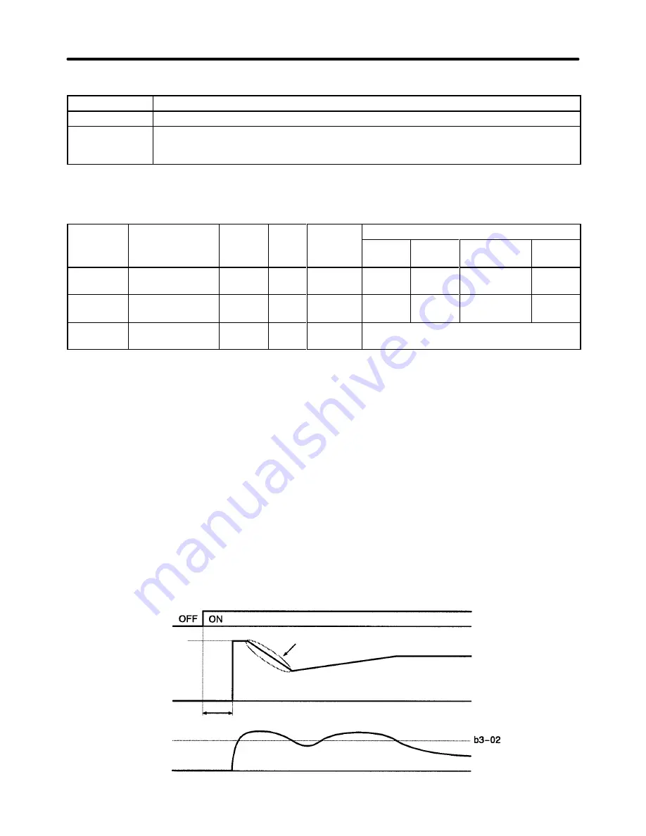
Speed Search Timing Chart
Run command
Maximum frequency
Output frequency
Output current
Deceleration time set for b3-03
Minimum baseblock time (L2-03)
Frequency reference
that is set
Advanced Operation
Chapter 6
Summary of Contents for SYSDRIVE 3G3FV
Page 1: ...USER S MANUAL High function General purpose Inverter SYSDRIVE 3G3FV Cat No I516 E1 4 ...
Page 16: ...Chapter 1 Introduction 1 1 Function 1 2 Nomenclature 1 3 New Functions 1 ...
Page 33: ...Chapter 2 Installation 2 1 Mounting 2 2 Wiring 2 ...
Page 112: ...Chapter 4 Trial Operation 4 1 Procedure 4 2 Operation Example 4 ...
Page 289: ...Chapter 7 Parameter Lists 7 1 Initialize Mode Parameters 7 2 Program Mode Parameter List 7 ...
Page 366: ...Chapter 9 Specifications 9 1 Inverter Specifications 9 2 Option Specifications 9 ...
Page 395: ...Chapter 10 Appendix 10 1 Notes on Using the Inverter for a Motor 10 ...