


6-34
H
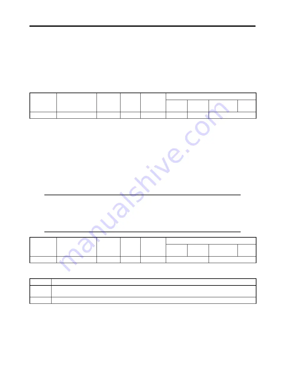
Setting the Slip Compensation Gain
With flux vector control, parameter C3-01 sets the motor’s temperature compensation gain. Adjust this
setting when a torque limit or torque control is being used and the output torque varies with the ambient
temperature. (There is no change to the compensation during speed control operation.)
Normally it isn’t necessary to change this setting. If the motor’s internal parameters change at higher
temperatures and the amount of slip increases, this parameter can be set to adjust the amount of slip
according to an internally calculated temperature rise. This parameter cannot be changed during op-
eration.
Parameter
Display name
Setting
Units
Default
Valid access levels*
number
p y
g
range
setting
V/f
Control
V/f with
PG
Open Loop
Vector
Flux
Vector
C3-01
Slip Come Gain
0.0 to 2.5 Factor
1.0
B
---
B
Note 1. B:
Basic or Advanced
---:
Not applicable.
Note 2. Adjust the setting if the output torque varies with the ambient temperature when a torque con-
trol or torque limit is being used. The compensation amount increases as the set value is
increased. This adjustment is not required during speed control operation.
6-3-8 Operation for Saturated Output Voltage
Previously, the accuracy of motor speed for vector control was greatly reduced when the
limit of the Inverter’s voltage output was approached (a voltage greater than that of the
input power supply cannot be output).
Set the following parameter to control the output voltage so that the limit will not be
reached, thus maintaining speed accuracy.
Parameter
Display name
Setting
Units
Default
Valid access levels
number
p y
g
range
setting
V/f
Control
V/f with
PG
Open Loop
Vector
Flux
Vector
C3-06
Output V limit
0, 1
---
0
Not applicable.
Advanced
Settings
Setting
Description
0
Disabled (There is no limit of output voltage saturation. Slip compensation is disabled when the
output voltage saturates.)
1
Enabled (Output voltage saturation is suppressed to keep the speed constantly.)
Note 1. Set the parameter to 1 if the accuracy of speed is required within the rated rpm range. This will
cause an increase of approximately 10% in the output current. Therefore, be sure that the
Inverter has more and sufficient output current.
Note 2. If the Inverter’s input voltage is extremely lower than the rated motor voltage, the accuracy of
the speed of the motor may not be maintained even with the output voltage suppressed.
Advanced Operation
Chapter 6
Summary of Contents for SYSDRIVE 3G3FV
Page 1: ...USER S MANUAL High function General purpose Inverter SYSDRIVE 3G3FV Cat No I516 E1 4 ...
Page 16: ...Chapter 1 Introduction 1 1 Function 1 2 Nomenclature 1 3 New Functions 1 ...
Page 33: ...Chapter 2 Installation 2 1 Mounting 2 2 Wiring 2 ...
Page 112: ...Chapter 4 Trial Operation 4 1 Procedure 4 2 Operation Example 4 ...
Page 289: ...Chapter 7 Parameter Lists 7 1 Initialize Mode Parameters 7 2 Program Mode Parameter List 7 ...
Page 366: ...Chapter 9 Specifications 9 1 Inverter Specifications 9 2 Option Specifications 9 ...
Page 395: ...Chapter 10 Appendix 10 1 Notes on Using the Inverter for a Motor 10 ...