


7-9
H
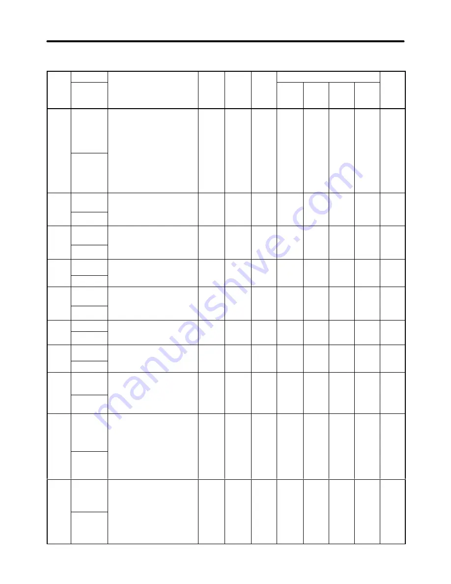
PID Control: b5
Para
meter
Name
Description
Setting
range
Default
setting
Chan-
ges
Control mode
Page
meter
No.
Display
name
range
setting
ges
during
opera-
tion
V/f
control
V/f
with
PG
Open
loop
vector
Flux
vector
b5-01
PID control
selection
0:
Disabled
1:
Enabled (Deviation is
D-controlled.)
2:
Enabled (Feedback value is
D-controlled.)
3:
Enabled (Frequency
ref PID control/
0 to 4
0
NO
A
A
A
A
6-50
PID Mode
ref PID control/
deviation is D-controlled.)
4:
Enabled (Frequency
ref PID control/
feedback value is
D-controlled.)
b5-02
Proportiona
l gain (P)
Sets P-control proportional gain
as a percentage.
Note: P control is not performed
0.00 to
25.00
1.00
OK
A
A
A
A
6-51
PID Gain
Note: P-control is not performed
when the setting is 0.00.
b5-03
Integral
time (I)
Sets I-control integral time in
1-second units.
Note: I control is not performed
0.0 to
360.0
1.0
OK
A
A
A
A
6-51
PID I Time
Note: I-control is not performed
when the setting is 0.0.
b5-04
Integral
limit (I)
Sets the I-control limit as a
percentage of the maximum
f
0.0 to
100.0
100.0
OK
A
A
A
A
6-51
PID I Limit
g
frequency.
b5-05
Differential
time (D)
Sets D-control differential time
in 1-second units.
Note: D control is not performed
0.00 to
10.00
0.00
OK
A
A
A
A
6-51
PID D Time
Note: D-control is not performed
when the setting is 0.00.
b5-06
PID limit
Sets the limit after PID-control
as a percentage of the
0.0 to
100 0
100.0
OK
A
A
A
A
6-51
PID Limit
as a percentage of the
maximum frequency.
100.0
b5-07
PID offset
adjustment
Sets the offset after PID-control
as a percentage of the
i
f
–100.0
to
100 0
0.0
OK
A
A
A
A
6-52
PID Offset
g
maximum frequency.
100.0
b5-08
PID primary
delay time
constant
Sets the time constant for low
pass filter for PID-control
outputs in 1-second units.
0.00 to
10.00
0.00
OK
A
A
A
A
6-52
PID Delay
Time
Note: Not usually necessary to
set.
b5-09
PID output
characteris-
tics selec-
tion
Selects whether the PID output
is reflected in positive or
negative characteristics.
0:
Positive characteristics
(Increased output frequency
increases feedback value)
0, 1
0
NO
A
A
A
A
6-52
Output
Level Sel
increases feedback value)
1:
Negative characteristics
(Increased output frequency
decreases feedback value)
b5-10
PID output
gain
Sets the multiplier for the final
calculation result of PID control
(PID control value).
Note: Normally it is not neces-
t
h
th f
t
0.0 to
25.0
1.0
NO
A
A
A
A
6-53
Output
Gain
y
sary to change the factory
settings. Adjust the level
of PID influence when us-
ing “Frequency reference
+ PID control.”
Parameter Lists
Chapter 7
Summary of Contents for SYSDRIVE 3G3FV
Page 1: ...USER S MANUAL High function General purpose Inverter SYSDRIVE 3G3FV Cat No I516 E1 4 ...
Page 16: ...Chapter 1 Introduction 1 1 Function 1 2 Nomenclature 1 3 New Functions 1 ...
Page 33: ...Chapter 2 Installation 2 1 Mounting 2 2 Wiring 2 ...
Page 112: ...Chapter 4 Trial Operation 4 1 Procedure 4 2 Operation Example 4 ...
Page 289: ...Chapter 7 Parameter Lists 7 1 Initialize Mode Parameters 7 2 Program Mode Parameter List 7 ...
Page 366: ...Chapter 9 Specifications 9 1 Inverter Specifications 9 2 Option Specifications 9 ...
Page 395: ...Chapter 10 Appendix 10 1 Notes on Using the Inverter for a Motor 10 ...