


6-44
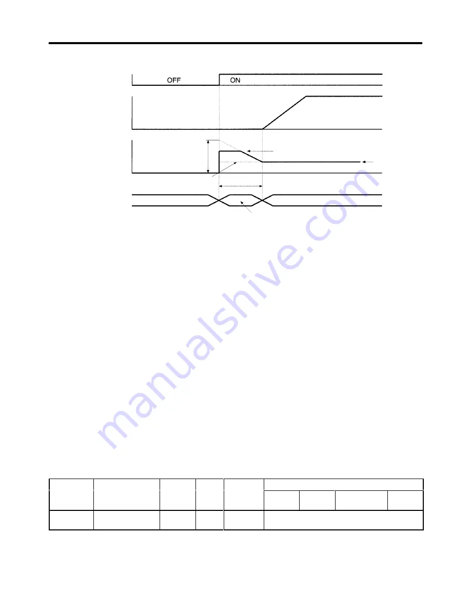
Timing Chart
Run command
Motor excitation current
Output frequency
Control mode
b2-08 = 100%
b2-03
Baseblock time
Speed control
Startup DC braking (initial excitation)
The motor excitation current is limited to the
motor’s rated current or 80% of the Inverter’s
rated current, whichever is smaller.
Magnetic flux
current of
motor under
control
b2-08
•
The magnetic flux in the motor can be brought up faster by setting b2-08 greater than 100% so that a
larger current flows when the “DC injection braking at startup” (initial excitation) function starts. The
magnetic flux will rise approximately twice as fast when b2-08 is set to 200%.
•
The magnetic flux in the motor will rise more slowly when b2-08 is set below 100%. (In general do not
set b2-08 below 100%, although operation with b2-08 = 0% is the same as b2-08 = 100% and the
magnetic flux is raised by the set DC injection braking current (b2-02).)
•
The sound generated from the motor during startup DC injection braking may increase as the magnet-
ic compensation value in b2-08 is increased.
•
If the delay before the start of control due to the DC injection braking (initial excitation) time at start
setting in b2-03 is too long, do not use this compensation function. Use the DC injection braking multi-
function input (set value: 60) instead and raise the motor magnetic flux in advance while the motor is
stopped.
H
Setting Speed Search (b3)
The speed search function finds the speed of a coasting motor and starts up smoothly from that speed. It
is effective in situations such as switching from a commercial power supply.
The speed search function applies a lower voltage than normal, and finds the speed at the current flow-
ing at that time. The speed search is determined to be completed when the frequency is lowered from
the maximum frequency (or a set frequency) and the current that is output falls below a fixed value.
When the speed search is completed, the speed is accelerated to the frequency reference according to
the acceleration time that has been set. For V/f with PG or flux vector control, detection occurs at the
motor speed with PG feedback.
Parameter
Display name
Setting
Units
Default
Valid access levels
number
p y
g
range
setting
V/f
Control
V/f with
PG
Open Loop
Vector
Flux
Vector
b3-01
Spd Srch at Start
0, 1
---
0 (See
note.)
Advanced
This parameter cannot be changed during operation.
Note When the control mode is switched, the factory default setting changes as follows:
V/f control: 0; V/f with PG: 1; open-loop vector 0; flux vector: 1
Advanced Operation
Chapter 6
Summary of Contents for SYSDRIVE 3G3FV
Page 1: ...USER S MANUAL High function General purpose Inverter SYSDRIVE 3G3FV Cat No I516 E1 4 ...
Page 16: ...Chapter 1 Introduction 1 1 Function 1 2 Nomenclature 1 3 New Functions 1 ...
Page 33: ...Chapter 2 Installation 2 1 Mounting 2 2 Wiring 2 ...
Page 112: ...Chapter 4 Trial Operation 4 1 Procedure 4 2 Operation Example 4 ...
Page 289: ...Chapter 7 Parameter Lists 7 1 Initialize Mode Parameters 7 2 Program Mode Parameter List 7 ...
Page 366: ...Chapter 9 Specifications 9 1 Inverter Specifications 9 2 Option Specifications 9 ...
Page 395: ...Chapter 10 Appendix 10 1 Notes on Using the Inverter for a Motor 10 ...